volkswagen Workshop Repair Guides

Volkswagen Workshop Service and Repair Manuals

Checking coolant temperature sender > < Checking throttle valve control part
Motronic injection and ignition system (6-Cyl. engine)
Checking components
Checking throttle valve potentiometer

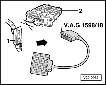
Vehicles ▸07.95

Vehicles08.95 ▸ , Checking throttle valve control unit

Special tools, testers, measuring instruments and auxiliary items required

  • ◆ Fault reader V.A.G 1551 or vehicle system tester V.A.G 1552 with cable V.A.G 1551/3
  • ◆ Test box V.A.G 1598/18
  • ◆ Hand multimeter V.A.G 1526 or multimeter V.A.G 1715
  • ◆ Adapter set V.A.G 1594
  • ◆ Current flow diagram

Note:

If the throttle valve potentiometer (G69) has been removed and installed or renewed, the automatic gearbox control unit (J217) and the throttle valve potentiometer must be matched to one another .

  • ‒ Connect the fault reader V.A.G 1551 (V.A.G 1552). Then switch ignition on and select engine control unit with the "Address word" 01.
    (Connecting fault reader and selecting engine control unit => Page 01-5 .)
 
→ Indicated on display:
Rapid data transfer     HELP
Select function XX
  • ‒ Press keys 0 and 8 for the function "Read measured value block" and confirm entry with Q key.
 
→ Indicated on display:
Read measured value block     HELP
Input display group number XXX
  • ‒ Press keys 0, 0 and 3 for "Display group number 3" and confirm entry with Q key.
 
→ Indicated on display:
(1...4 = Display zones)
Read measured value block 3     ⇒
     1     2     3     4
  • ‒ Read off throttle valve angle in display zone 3.

Throttle valve angle at idling stop
     Specification: 9...19 <°

  • ‒ Slowly open throttle valve fully and observe angle display in display zone 3. The figure must increase uniformly over
         the complete range.

Throttle valve angle at full throttle stop
     Specification: 90...101 <°

  • ‒ Press the ⇒key.
  • ‒ Input 06 for "End output" and confirm with Q.
 
V29-0062

If the specifications are not attained or do not increase uniformly:

  • ‒ Switch off ignition.
  • ‒ → Connect test box V.A.G 1598/18 to control unit wiring loom.
  • ‒ Measure throttle valve positioner resistance on test box between
         Socket 33+socket 41
         Specification: 1.50...2.50 kω
  • ‒ Measure resistance on test box with throttle valve closed between
         Socket 33+socket 40
         Specification: 0.70...1.30 kω
  • ‒ Open throttle valve and specification must rise.
  • ‒ Check resistance on test box with throttle valve closed between
         Socket 40+socket 41
         Specification: 2.50...3.50 kω
  • ‒ Open throttle valve again and the specification must drop.

If the specifications are not obtained:

  • ‒ Renew throttle valve potentiometer

Checking coolant temperature sender > < Checking throttle valve control part