volkswagen Workshop Repair Guides

Volkswagen Passat Workshop Service and Repair Manuals

Checking throttle valve potentiometer > < Checking air mass meter
Motronic injection and ignition system (6-Cyl. engine)
Checking components
Checking throttle valve control part

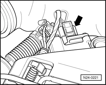
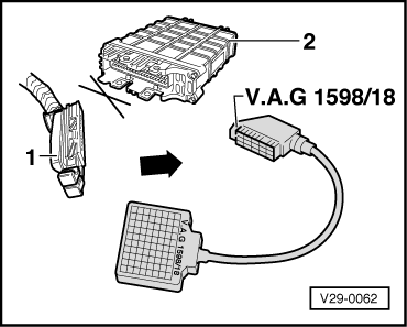
Vehicles08.95 ▸

Components of the throttle valve control part (J338):
Throttle valve positioner (V60), throttle valve positioner potentiometer (G127), throttle valve potentiometer (G69) and idling switch (F60)

Note:

If the throttle valve control part is replaced, the new control part must without fail be matched to the engine control unit .

Special tools, testers, measuring instruments and auxiliary items required

  • ◆ Fault reader V.A.G 1551 or vehicle system tester V.A.G 1552 with cable V.A.G 1551/3
  • ◆ Test box V.A.G 1598/18
  • ◆ Hand multimeter V.A.G 1526 or multimeter V.A.G 1715
  • ◆ Adapter set V.A.G 1594
  • ◆ Current flow diagram

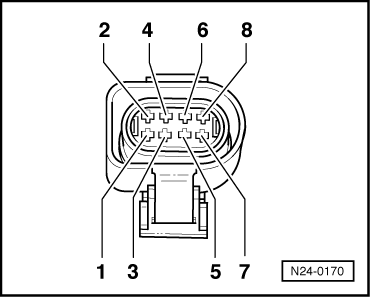
Checking idling switch (F60)

Test conditions

  • ● Throttle cable adjustment OK, checking:

=> Repair group 20; Removing and installing parts of fuel supply system; Adjusting throttle mechanism

  • ‒ Connect the fault reader V.A.G 1551 (V.A.G 1552). Then switch ignition on and select engine control unit with the "Address word" 01.
    (Connecting fault reader and selecting engine control unit => Page 01-5 .)
 
→ Indicated on display:
Rapid data transfer     HELP
Select function XX
  • ‒ Press keys 0 and 8 for the function "Read measured value block" and confirm entry with Q key.
 
→ Indicated on display:
Read measured value block     HELP
Input display group number XXX
  • ‒ Press keys 0, 0 and 5 for "Display group number 5" and confirm entry with Q key.
 
→ Indicated on display:
(1...4 = Display zones)
Read measured value block 5     ⇒
     1     2     3     4
  • ‒ Check the operating mode display in display zone 4.
         Display: Idling
  • ‒ Slowly open throttle valve. After free travel, a stop is reached when opening throttle valve further the 4th position from left must jump to part throttle
         Display: Part throttle

If the specifications are not obtained:

Display

Cause

Continuation of check

Part throttle

Open circuit or short to positive

=> Page 24-37

Idling

Short to earth

=> Page 24-39

Continuation of check when display shows part throttle

 
N24-0221
  • ‒ → Separate 8 pin connector to throttle valve control part -arrow-.
 
N24-0170
  • ‒ → Bridge connector contacts 3+7 with aux. cables from V.A.G 1594 and observe display.

Display Idling:

  • ‒ Press the ⇒key.
  • ‒ Press keys 0 and 6 for the function "End output" and confirm entry with the Q key.
  • ‒ Switch off ignition.
  • ‒ Replace throttle valve control part (J338).

Display Part throttle:

  • ‒ Press the ⇒key.
  • ‒ Press keys 0 and 6 for the function "End output" and confirm entry with the Q key.
  • ‒ Switch off ignition.
  • ‒ Check voltage supply of throttle valve control part and wiring to control unit => Page 24-48 .

If the voltage supply and wiring is OK:

  • ‒ Renew engine electronics control unit => Page 24-112 .
 
N24-0221

Continuation of check when display constantly shows idling

  • ‒ → Separate 8 pin connector to throttle valve control part -arrow-.

Display Part throttle:

  • ‒ Press the ⇒key.
  • ‒ Press keys 0 and 6 for the function "End output" and confirm entry with the Q key.
  • ‒ Switch off ignition.
  • ‒ Replace throttle valve control part (J338).

Display Idling:

  • ‒ Press the ⇒key.
  • ‒ Press keys 0 and 6 for the function "End output" and confirm entry with the Q key.
  • ‒ Switch off ignition.
  • ‒ Check voltage supply of throttle valve control part and wiring to control unit => Page 24-48 .

If the voltage supply and wiring is OK:

  • ‒ Renew engine electronics control unit => Page 24-112 .

Checking throttle valve positioner (V60) and sender for throttle valve positioner (G127)

Test conditions

  • ● Coolant temperature at least 85 °C.

Test sequence

  • ‒ Connect fault reader V.A.G 1551 (V.A.G 1552). Start engine and select "Address word" 01 of engine control unit. When doing this the engine must be running at idling speed.
    (Connecting fault reader and selecting engine control unit => Page 01-5 .)
 
→ Indicated on display:
Rapid data transfer     HELP
Select function XX
  • ‒ Press keys 0 and 8 for the function "Read measured value block" and confirm entry with Q key.
 
→ Indicated on display:
Read measured value block     HELP
Input display group number XXX
  • ‒ Press keys 0, 0 and 1 for "Display group number 1" and confirm entry with Q key.
 
→ Indicated on display:
(1...4 = Display zones)
Read measured value block     1     ⇒
     1     2     3     4
  • ‒ Check whether the coolant temperature is above 85 °C in display zone 2.
  • ‒ Change to display group 6 as follows:
  • ‒ Press C key.
 
→ Indicated on display:
Read measured value block     HELP
Input display group number XXX
  • ‒ Press keys 0, 0 and 6 for "Display group number 6" and confirm entry with Q key.
 
→ Indicated on display:
(1...4 = Display zones)
Read measured value block 6     ⇒
     1     2     3     4
  • ‒ Check throttle valve positioner duty cycle at idling stop in display zone 3.
         Specification: 65...80 %

If the specification is not obtained:

  • ‒ Press the ⇒key.
  • ‒ Press keys 0 and 6 for the function "End output" and confirm entry with the Q key.
  • ‒ Switch off ignition.
 
N24-0221
  • ‒ → Separate 8 pin connector to throttle valve control part -arrow-.
  • ‒ Measure throttle valve positioner resistance between connector contacts 1+2.
         Specification: 3...200 ω
  • ‒ Check voltage supply of throttle valve control part and wiring to control unit => Page 24-48 .

If no fault is detected:

  • ‒ Replace throttle valve control part (J338).

Checking throttle valve potentiometer (G69)

Test conditions

  • ● Coolant temperature at least 85 °C.

Test sequence

  • ‒ Connect the fault reader V.A.G 1551 (V.A.G 1552). Then switch ignition on and select engine control unit with the "Address word" 01.
    (Connecting fault reader and selecting engine control unit => Page 01-5 .)
 
→ Indicated on display:
Rapid data transfer     HELP
Select function XX
  • ‒ Press keys 0 and 8 for the function "Read measured value block" and confirm entry with Q key.
 
→ Indicated on display:
Read measured value block     HELP
Input display group number XXX
  • ‒ Press keys 0, 0 and 1 for "Display group number 1" and confirm entry with Q key.
 
→ Indicated on display:
(1...4 = Display zones)
Read measured value block     1     ⇒
     1     2     3     4
  • ‒ Check whether the coolant temperature is above 85 °C in display zone 2.
  • ‒ Change to display group 3 as follows:
  • ‒ Press C key.
 
→ Indicated on display:
Read measured value block     HELP
Input display group number XXX
  • ‒ Press keys 0, 0 and 3 for "Display group number 3" and confirm entry with Q key.
 
→ Indicated on display:
(1...4 = Display zones)
Read measured value block 3     ⇒
     1     2     3     4
  • ‒ Read off throttle valve angle in display zone 3.
  • ‒ Slowly open throttle valve fully and observe angle display in display zone 3. The figure must increase uniformly over
         the complete range.
  • ‒ Press the ⇒key.
  • ‒ Press keys 0 and 6 for the function "End output" and confirm entry with the Q key.
  • ‒ Switch off ignition

Note:

The displayed figure is dependent on the tolerances of the throttle valve potentiometer and does not correspond to the actual opening angle.

If the figure does not increase uniformly:

  • ‒ Replace throttle valve control part (J338).

If the display constantly shows 0 <° or is above 90 <°:

Display

Cause

Continuation of check

0 <°

Open circuit or short to positive

=> Page 24-44

above
90 <°

Short to earth

=> Page 24-47

Continuation of check when display 0 <°:

 
N24-0221
  • ‒ → Separate 8 pin connector to throttle valve control part -arrow-.
 
N24-0170
  • ‒ → Bridge connector contacts 5+7 with auxiliary cables from V.A.G 1594 and observe display.

Display above 90 <°:

  • ‒ Press the ⇒key.
  • ‒ Press keys 0 and 6 for the function "End output" and confirm entry with the Q key.
  • ‒ Switch off ignition.
  • ‒ Replace throttle valve control part (J338).

Display 0 <°:

  • ‒ Press the ⇒key.
  • ‒ Press keys 0 and 6 for the function "End output" and confirm entry with the Q key.
  • ‒ Switch off ignition.
  • ‒ Check voltage supply of throttle valve control part and wiring to control unit => Page 24-48 .
 
N24-0221

If the voltage supply and wiring is OK:

  • ‒ Renew engine electronics control unit => Page 24-112 .

Continuation of check when display is above 90 <°:

  • ‒ → Separate 8 pin connector to throttle valve control part -arrow-.

Display 0 <°:

  • ‒ Press the ⇒key.
  • ‒ Press keys 0 and 6 for the function "End output" and confirm entry with the Q key.
  • ‒ Switch off ignition.
  • ‒ Replace throttle valve control part (J338).

Display above 90 <°:

  • ‒ Press the ⇒key.
  • ‒ Press keys 0 and 6 for the function "End output" and confirm entry with the Q key.
  • ‒ Switch off ignition.
  • ‒ Check voltage supply of throttle valve control part and wiring to control unit => Page 24-48 .

If the voltage supply and wiring is OK:

  • ‒ Renew engine electronics control unit => Page 24-112 .
 
N24-0221

Checking voltage supply and wiring to control unit

  • ‒ → Separate 8 pin connector to throttle valve control part -arrow-.
 
N24-0170
  • ‒ → Connect multimeter to measure voltage at connector contacts 4+7.
  • ‒ Switch on ignition.
         Specification: min. 4.5 V
  • ‒ Switch off ignition.
  • ‒ Connect multimeter to measure voltage at connector contacts 3+7.
  • ‒ Switch on ignition.
         Specification: min. 9 V
  • ‒ Switch off ignition.
 
V29-0062
  • ‒ → Connect test box V.A.G 1598/18 to control unit wiring loom.
 
N24-0170
  • ‒ → Check wiring between test box and 8 pin connector for open circuit according to current flow diagram.
         Contact 1+socket 27
         Contact 2+socket 53
         Contact 3+socket 10
         Contact 4+socket 41
         Contact 5+socket 40
         Contact 7+socket 33
         Contact 8+socket 62
         Wire resistance: Max. 1.5 ω
  • ‒ Additionally check wires for short to one another.
         Specification: ∞ω

If no wiring fault is detected:

  • ‒ Check engine control unit voltage supply => Page 24-108 .

Is the voltage supply and activation OK:

  • ‒ Renew engine electronics control unit => Page 24-112 .

Checking throttle valve potentiometer > < Checking air mass meter