volkswagen Workshop Repair Guides

Volkswagen Workshop Service and Repair Manuals

Removing and installing crankshaft > < Removing and installing counterbalance shaft and retaining frame
3-cyl. diesel engine, Mechanics
Removing and installing counterbalance shaft and retaining frame
Removing and installing counterbalance shaft
 
W13-0083

Special tools, workshop equipment, test and measuring appliances and auxiliary items required

  • ◆ T10060 Retaining pin
  • ◆ T10061 Socket
  • ◆ V.A.G 1331 Torque wrench (5...50 Nm)
  • ◆ V.A.G 1332 Torque wrench (40...200 Nm)
  • ◆ Spanner (24/27 mm AF)

Removing

  • ‒ Remove ribbed belt .
  • ‒ Remove toothed belt => Page15-10.
  • ‒ Remove sump => Page 17-17.
  • ‒ Remove sealing flange, pulley side => Page 13-22.
  • ‒ Remove securing bolts from cover.
  • ‒ Unclip cover from retaining frame.
 
N13-0539
  • ‒ → Lock chain tensioner with retaining pin T10060 -arrow-.
  • ‒ Unbolt sprocket/idler roller -1- from retaining frame.
  • ‒ Remove securing bolts -2- from chain tensioner and remove it.
  • ‒ Remove chain from sprockets and lay it aside on a clean surface.
 
N13-0545
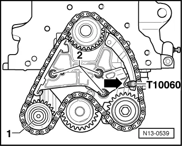
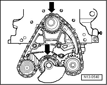
  • ‒ → Block the counterbalance shaft as shown with a spanner (24/27 mm AF) -1-.

Note:

When blocking the counterbalance shaft, make sure that the spanner is centred on the counterbalance weight and at right angles to counterbalance shaft.

  • ‒ Loosen securing bolt -2- of counterbalance weight.

Note:

Only loosen counterbalance weight securing bolt -2-; do not remove it.

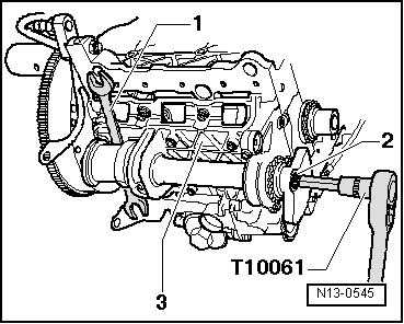
  • ‒ Unbolt retaining frame -3- from cylinder block and remove retaining frame with counterbalance shaft.
  • ‒ Lay retaining frame aside on a clean surface.
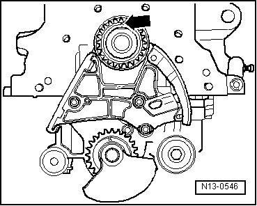
  • ‒ Remove securing bolt from counterbalance shaft.
  • ‒ Remove counterbalance weight and sprocket from counterbalance shaft.
  • ‒ Turn the counterbalance shaft so that it can be removed from the bearing.

Installing

  • ‒ Oil bearing's running surfaces.
  • ‒ Set counterbalance shaft in bearing.
  • ‒ Fit sprocket and counterbalance weight on counterbalance shaft.

Note:

The assembly of the sprocket and the counterbalance weight is possible in one position only.

  • ‒ Hand tighten securing bolt for counterbalance weight and sprocket.
  • ‒ Tighten retaining frame to cylinder block by hand so that there is no play.

Notes:

  • ◆ When fitting retaining frame, ensure that the dowel sleeve is inserted in the cylinder block and the O ring is fitted in the retaining frame.
  • ◆ Align the retaining frame so that it fits flush with the outer edge of the cylinder block on the pulley end.
  • ‒ Bolt retaining frame with counterbalance shaft to cylinder block
        Tightening torque: 20 Nm.
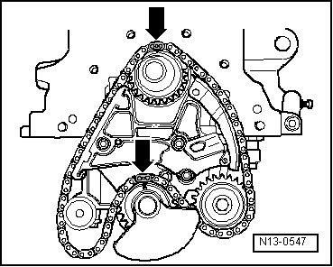
  • ‒ Check that retaining frame aligns flush with outer edge of cylinder block on the pulley end.
 
N13-0545
  • ‒ → Block counterbalance shaft as shown with spanner (24/27 mm AF) -1-.

Note:

When blocking the counterbalance shaft, make sure that the spanner is centred on the counterbalance weight and at right angles to counterbalance shaft.

  • ‒ Tighten counterbalance weight securing bolt -2-
        Tightening torque: 100 Nm + 1/4 turn (90 °) further.

Note:

The securing bolt is a stretch bolt am must always be replaced.

  • ‒ Install chain tensioner
        Tightening torque: 8 Nm + 1/4 turn (90°) further.

Note:

The chain tensioner securing bolts are stretch bolts and must be renewed without exception.

  • ‒ Clean chain with a lint-free cloth.
 
N13-0546
  • ‒ → Ensure that mark on crankshaft sprocket -arrow- is at top.
 
N13-0547
  • ‒ → Lay chain over crankshaft sprocket, oil pump sprocket and counterbalance shaft sprocket. Ensure that the marks on the crankshaft sprocket and counterbalance sprocket align with the colour-coded chain links -arrows-.

Note:

The colour-coded chain links are marked with a notch.

  • ‒ Engage idler sprocket in chain and tighten idler sprocket to retaining frame
        Tightening torque: 20 Nm.
  • ‒ Remove retaining pin T10060 from chain tensioner.
 
N13-0540
  • ‒ → Check that marks on crankshaft sprocket and counterbalance shaft sprocket align with the colour-coded chain links -arrows-.

Note:

The colour-coded chain links are marked with a notch.

  • ‒ Install pulley end sealing flange => Page 13-22.
  • ‒ Install counterbalance shaft cover
        Tightening torque: 5 Nm.

Notes:

  • ◆ Before installing cover, oil O ring of oil pump as well as shaft on inside of cover.
  • ◆ Ensure proper seating of sealing strip in cover.
  • ◆ When installing cover, ensure that cover engages in retaining frame.
  • ‒ Install sump => Page 17-17.
  • ‒ Install and tension toothed belt => Page 15-10.
  • ‒ Install ribbed belt => Page 13-16.

Removing and installing crankshaft > < Removing and installing counterbalance shaft and retaining frame