
Polo Mk3
 |
|
|
Up to 26.04.95 From 27.04.95
|
 |
|
|
 |
|
Vehicles with cable selector control:
|
 |
|
|
 |
|
=> Repair group 27; Removing and installing starter. For vehicles with an oval air cleaner:
|
 |
|
|
 |
|
Vehicles with petrol engine and rod selector mechanism |
 |
|
|
 |
|
Vehicles with petrol engine and cable selector mechanism |
 |
|
|
 |
|
|
 |
|
|
Continuation for all vehicles
|
 |
|
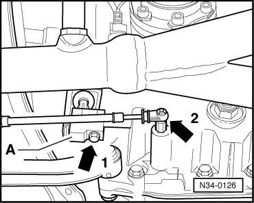
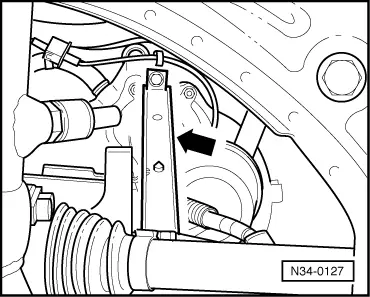
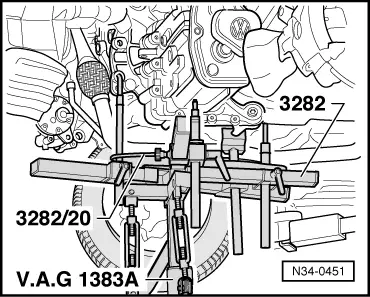
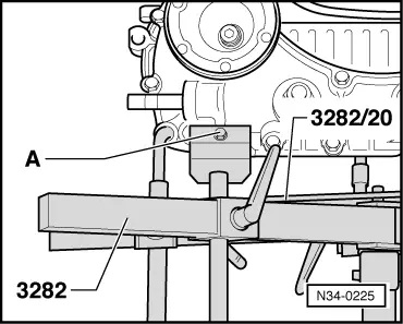
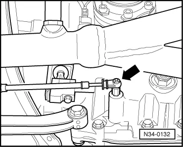
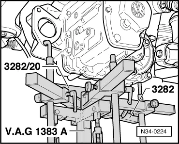
The pin hole is required to secure gearbox to gearbox mounting 3282 . |
 |
|
|
|
|
|
 |
|
|
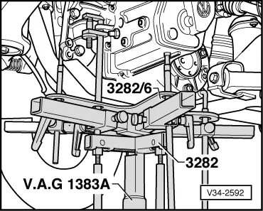
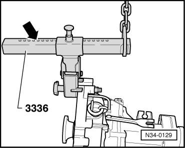
Transporting the automatic gearbox Special tool 3336 may be used to transport the gearbox and also when setting up gearbox mounting 3282.
|
 |
|
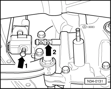
No. of holes visible = 9
Installing Note: Modifications on vehicles with Diesel engine .
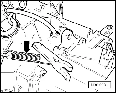
The clutch plate must be able to slide lightly to and fro on the input shaft.
|
|
|
|
|
|
|
|
|
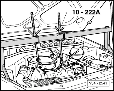
Warning!
Do not remove support bar 10-222A until the bolts securing the left-hand gearbox console have been tightened to torque setting.
|
|
|
=> Repair group 27; Removing and installing starter.
|
|
|
|
 |
|
|
|
|
Vehicles with cable selector control:
|
|
|
|
|
|
|
 |
|
|
Notes:
Up to 26.04.95 =>from Page 30-10 From 27.04.95 =>from Page 30-17
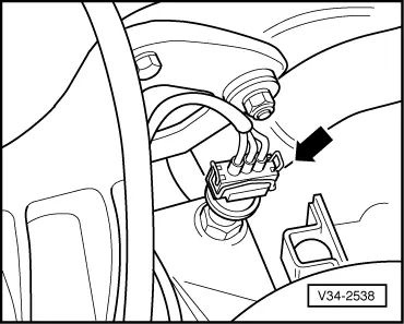
Note: Note radio coding for vehicles with coded radio.
Rod selector mechanism . Cable selector mechanism => Page 34-41 Tightening torques Gearbox to engine |
 |
|||||||||||||||||||||||||||||
|
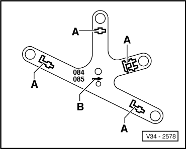
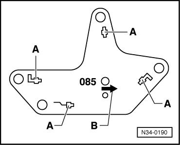
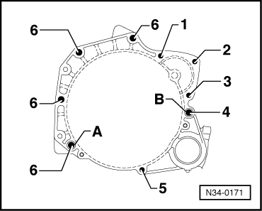
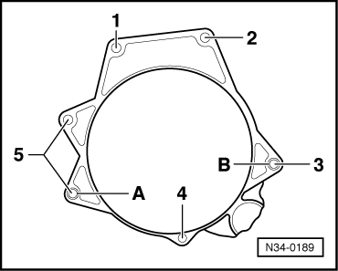
→ Engine block of cast iron (painted black)
Items A + B - Dowel sleeves Gearbox to engine |
 |
|||||||||||||||||||||||||||||||||
|
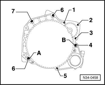
→ Engine block of aluminium (metallic brilliant)
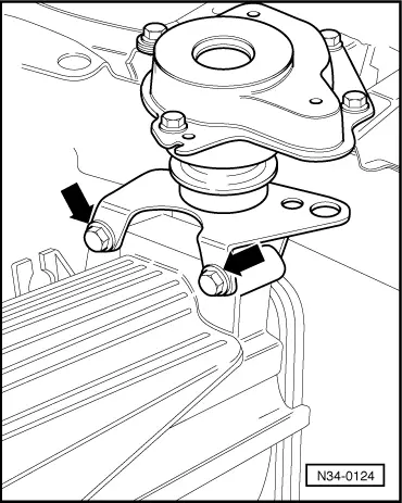
1) Flywheel shield securing bolts Items A + B - Dowel sleeves Assembly mountings |
|
||||||||||||
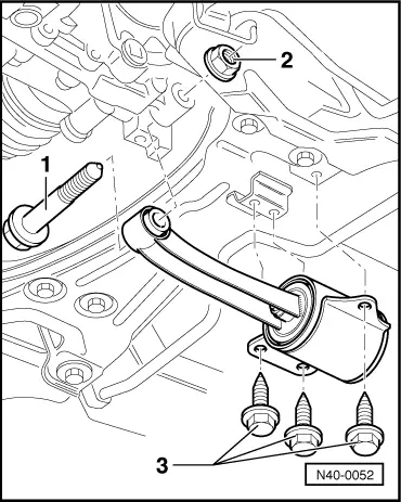
Modification from 12.96 From vehicle identification No.: 6N ZVW 133102 modified hexagon bolts -3- have been introduced.
| ||||||||||||
|
|||
| |||
|
|||||||||
| |||||||||
|
|
|
The following modifications should be noted on vehicles with Diesel engine:
|
|
|
|
|
|
|
 |
|
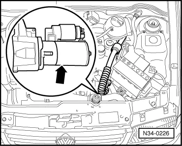
|
→ Install starter (arrow) before installing gearbox. => Repair group 27; Removing and installing starter. The clutch housing flange and the securing bolts have been matched to the Diesel engine. Tightening torques |
 |
|||||||||||||||||||||||||
|
→ Gearbox to engine
1) Flywheel shield securing bolts 2) Also starter to gearbox Items A + B = Dowel sleeves |