volkswagen Workshop Repair Guides

Volkswagen Workshop Service and Repair Manuals

Adjusting selector finger and selector sleeve > < Dismantling and assembling sequence
5-speed manual gearbox 085
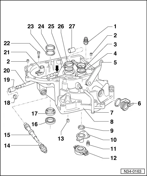
Servicing clutch housing
 
N34-0163
  • Locking bolt, 40 Nm
    • ◆ For selector shaft
  • Dowel sleeve
    • ◆ Qty. 2
  • Outer race/taper roller bearing
    • ◆ For input shaft
    • ◆ Removing and installing
  • Shim
    • ◆ For input shaft
    • ◆ Determining thickness => Page 35-13
  • Release shaft
    • ◆ Removing and installing
      => Page 30-28
  • Sealing bolt with plug
 
N34-0163
  • Breather pipe
  • Clutch housing
    • ◆ If replaced: =>Observe adjustment overview, Page 39-22
    • ◆ Modifications:
      Gearboxes for vehicles with cable selector mechanism, additional threaded mounting point => Fig.1
    • ◆ Different gearbox mounting flanges for petrol and Diesel engines => Parts catalogue
  • Input shaft oil seal
    • ◆ Removing => Fig.3
    • ◆ Installing => Fig. 4
  • Guide sleeve
  • Bolt, 20 Nm
  • Release bearing
    • ◆ Removing and installing
      => Page 30-29
 
N34-0163
  • Mounting bush
    • ◆ Only in conjunction with petrol engine
    • ◆ Removing => Fig.5
    • ◆ Installing => Fig. 6
  • Guide bush
  • Drive shaft with pinion
    • ◆ For speedometer
  • Flange shaft oil seal
    • ◆ Removing => Fig.7
    • ◆ Installing => Fig. 8
    • ◆ Renewing with gearbox installed => page 39-5
  • Sleeve
    • ◆ For oil seal (Item 16 )
    • ◆ Removing => Fig.9
    • ◆ Installing => Fig. 10
  • Oil seal
    • ◆ For selector shaft
    • ◆ Carefully lever out using screwdriver => fig.11
    • ◆ Installing => fig.12
    • ◆ Can be renewed with gearbox installed
 
N34-0163
  • Front ball sleeve
    • ◆ For selector shaft
    • ◆ Removing and installing
      =>Fig.13
  • Selector shaft
    • ◆ Installation position: The countersunk (arrow) points towards selector sleeve (Item 21 )
    • ◆ Check seat of bearing and inner racer of roller bearing for burrs and damage
    • ◆ Grease sliding surfaces with
      MoS2 grease
    • ◆ Adjusting => Page 34-114
    • ◆ Modification:
      Gearboxes for vehicles with cable selector control, new selector finger mounting => Fig.2
  • Selector sleeve
  • Bolt, 25 Nm
  • Shim
    • ◆ For differential
    • ◆ Determining thickness => Page 39-23
 
N34-0163
  • Outer race/taper roller bearing
    • ◆ For differential
    • ◆ Removing and installing
      => Page 39-8
    • ◆ If replaced: Adjust differential
      => Page 39-23
  • Shim
    • ◆ For output shaft
    • ◆ Determining thickness => Page 35-36
  • Outer race/taper roller bearing
    • ◆ For output shaft
    • ◆ Removing and installing
      => Page 35-18
  • Rear ball sleeve
    • ◆ For selector shaft
    • ◆ Removing and installing
      =>Fig.14
 
N34-0309

→ Fig.1     Modified clutch housing for gearboxes used in conjunction with cable selector mechanism

The clutch housing is equipped with two threaded mounting points (arrows A and B) for mounting the relay lever/selector cable bracket.

 
N34-0308

→ Fig.2     Modified selector shaft for gearboxes used in conjunction with cable selector mechanism

The selector shaft has only one recess (arrow) to accept the selector finger securing bolt as opposed to previous selector shaft.

Note:

The selector shaft cannot be installed in previous gearboxes.

 
V34-2767

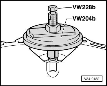
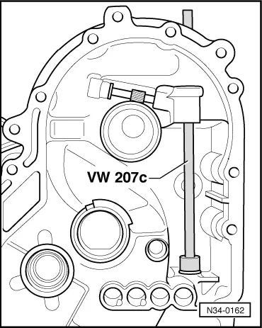
→ Fig.3     Pulling out output shaft oil seal.

 
N34-0160

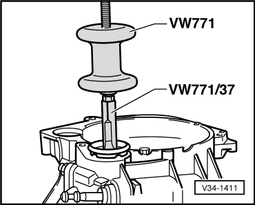
→ Fig.4     Driving in output shaft oil seal.

Installation position:

2.5 mm below housing upper surface.

 
V34-0182

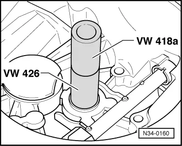
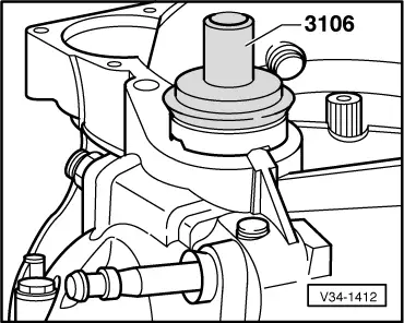
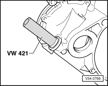
→ Fig.5     Pulling out starter bush.

 
V34-1223

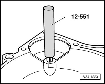
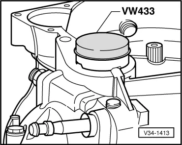
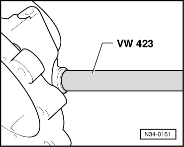
→ Fig.6     Driving in starter bush.

  • ‒ Lubricate bush mounting before driving in.
 
V34-1411

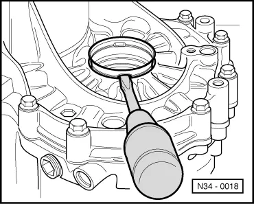
→ Fig.7     Pulling in flange shaft oil seal.

 
V34-1412

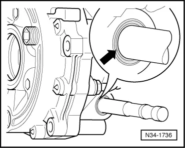
→ Fig.8     Driving in flange shaft oil seal.

  • ‒ Use the relevant side of the tool for the seals.
  • ‒ Fill space between seal and dust lip with multi-purpose grease.
 
N34-0018

→ Fig.9     Lever out sleeve with screwdriver

 
V34-1413

→ Fig.10     Driving in sleeve

 
N34-1736

→ Fig.11     Levering out seal using screwdriver

  • ‒ Remove selector shaft.
  • ‒ To prevent damage to the selector shaft, wrap thin layer of insulation tape around it.
  • ‒ Push selector shaft in onto stop.
  • ‒ Carefully punch a hole in the middle of the seal (arrow) using a small screwdriver.
  • ‒ Then lever out the seal using a slightly larger screwdriver.
 
V34-2769
  • ‒ Remove insulation tape and check selector shaft for damage.

→ Fig.12     Press in seal onto stop

  • ‒ Lightly oil outer circumference of oil seal.
  • ‒ Fill space between sealing lip and dust lip with grease G 052 128 A1.
  • ‒ Carefully push seal over chamfer of selector shaft in a twisting motion.
 
N34-0161

→ Fig.13     Removing and installing front ball sleeve

Installation position:

10 mm below housing upper surface.

 
N34-0162

→ Fig.14 Removing and installing rear ball sleeve

Installation position:

The ball sleeve must be flush in the rear area with the mounting eye.

Adjusting selector finger and selector sleeve > < Dismantling and assembling sequence