
Polo Mk3
|
Dismantling and assembling gearbox
Dismantling and assembling planetary gearbox
|
 |
|
|
 |
|
Dismantling planetary gearbox |
 |
|
|
 |
|
|
 |
|
|
 |
|
|
 |
|
|
 |
|
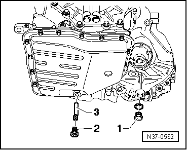
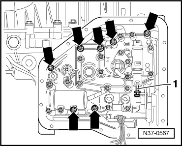
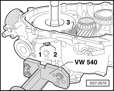
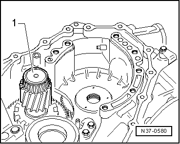
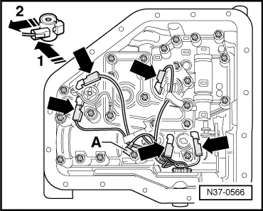
When removing the valve chest the manual selector valve -1- remains in valve chest.
|
 |
|
|
Gearbox from manufacture date 07.99
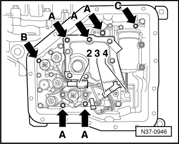
When removing the valve chest, the manual selector valve -4- remains in the valve chest.
Continued for all gearboxes |
 |
|
|
 |
|
|
 |
|
|
 |
|
|
 |
|
|
 |
|
|
 |
|
 |
|
|
 |
|
|
 |
|
|
 |
|
|
 |
|
|
 |
|
|
 |
|
|
 |
|
Gearbox up to manufacture date 06.99 |
 |
|
Continued for all gearboxes |
 |
|
Gearbox up to manufacture date 06.99 |
 |
|
|
 |
|
|
 |
|
|
 |
|
|
 |
|
|
Gearbox from manufacture date 07.99
|
 |
|
|
 |
|
|
|
|
|
Assembling planetary gearbox up to manufacture date 06.99 Assembling planetary gearbox up to manufacture date 07.99 => page 37-135 . Insert axial needle bearing in its fitted position
|
|
|
|
|
|
|
|
|
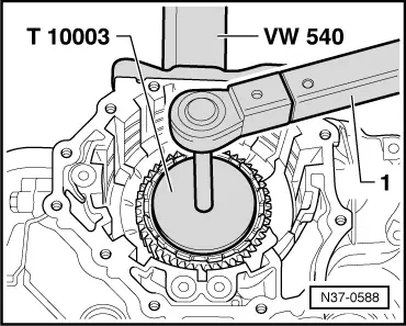
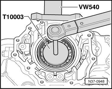
It should only be possible to turn the planet carrier anti-clockwise (free- wheel open). |
 |
|
|
 |
|
|
 |
|
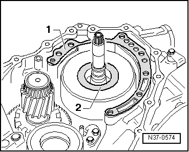
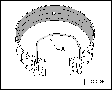
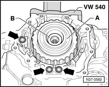
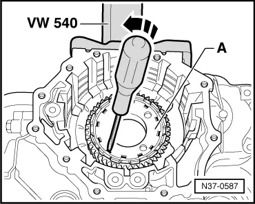
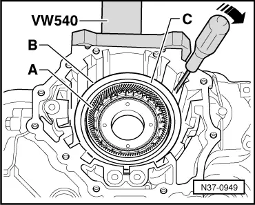
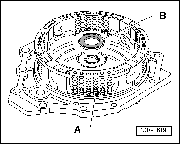
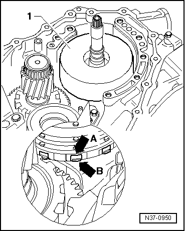
There are four guide pins -A- which are thicker and hold the spring cage in place.
Fit axial needle bearing in correct position (blackened surface remains visible) on the cover. |
 |
|
|
|
|
|
|
|
|
|
|
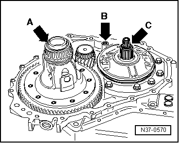
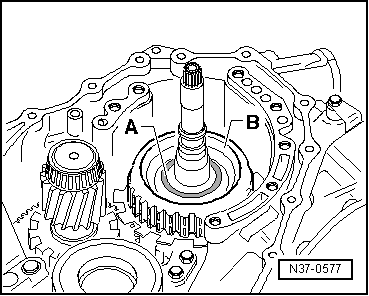
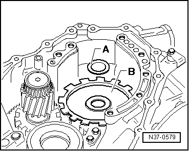
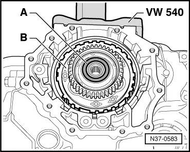
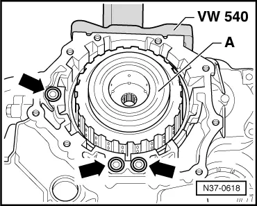
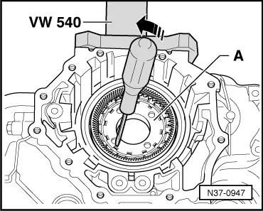
Place roller bearing -A- in correct position (smooth surface remains visible) on the large sun wheel. |
|
|
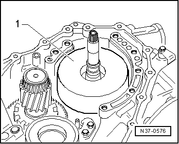
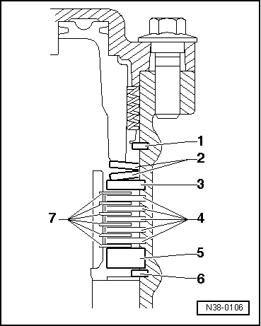
Place axial needle bearing -1- in correct fitted position (blackened side remains visible) onto the input shaft. |
|
|
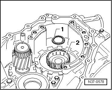
Place axial needle bearing -A- in correct fitted position (blackened surface remains visible) into the 1st to 3rd gear clutch. If individual parts of the planetary gearbox have been replaced the axial needle bearing must be recalculated =>Adjusting clutch clearance, from page 37-155 . |
|
|
|
|
|
If individual parts of the planetary gearbox have been replaced the size of the shim must be recalculated =>Adjusting clutch clearance, from page 37-155 .
|
|
|
|
|
|
|
|
|
|
|
|
|
 |
|
|
|
|
|
 |
|
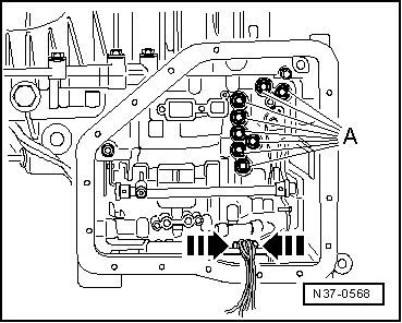
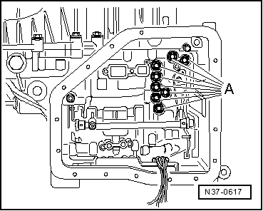
The cable colours are the same as the relevant solenoid valve colours.
|
|
|
|
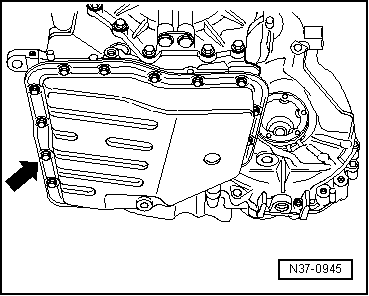
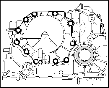
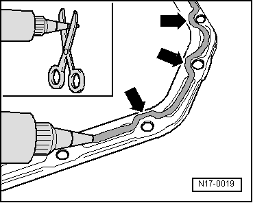
Apply sealant D176 404 A2 as follows to the oil pan:
|
|
|
 |
|
|
Assembling planetary gearbox from manufacture date 07.99 Insert axial needle bearing in its fitted position
|
|
|
|
|
|
|
 |
|
|
|
|
It should only be possible to turn the planet carrier anti-clockwise (free- wheel open). |
|
|
|
|
|
|
|
|
There are four guide pins -A- which are thicker and hold the spring cage in place.
Fit axial needle bearing in correct position (blackened surface remains visible) on the cover. |
|
|
|
|
|
|
|
|
|
|
|
Place roller bearing -A- in correct position (smooth surface remains visible) on the large sun wheel. |
|
|
Place axial needle bearing -1- in correct fitted position (blackened side remains visible) onto the input shaft. |
|
|
Place axial needle bearing -A- in correct fitted position (blackened surface remains visible) into the 1st to 3rd gear clutch. If individual parts of the planetary gearbox have been replaced the axial needle bearing must be recalculated =>Adjusting clutch clearance, from page 37-155 . |
 |
|
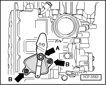
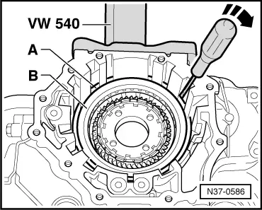
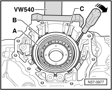
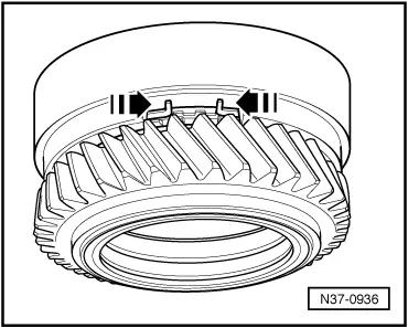
Cut outs -A- must be placed over tabs -B-. |
|
|
If individual parts of the planetary gearbox have been replaced the size of the shim must be recalculated =>Adjusting clutch clearance, from page 37-155 .
|
|
|
|
|
|
|
|
|
|
|
|
|
|
|
|
 |
|
Apply sealant D176 404 A2 as follows to the oil pan: |
|
|
|
|
|