volkswagen Workshop Repair Guides

Volkswagen Workshop Service and Repair Manuals

Checking throttle valve control part > < Checking Lambda probe heating before catalyst
Motronic inj. and ignition system (2-valve, roller rocker finger)
Checking components
Checking Lambda probe heating after catalyst

Only engines which conform to EU 4 standard (engine code AKP, AUC, AUD)

Special tools, workshop equipment, testers, measuring instruments and auxiliary items required

  • ◆ Test box V.A.G 1598/22
  • ◆ Fault reader V.A.G 1551 or vehicle system tester V.A.G 1552 with cable V.A.G 1551/3A
  • ◆ Hand multimeter V.A.G 1526 or multimeter V.A.G 1715
  • ◆ Adapter set V.A.G 1594
 
N24-0831
  • ◆ Current flow diagram

Check conditions

  • ● → Fuse No. 1 must be OK.
  • ● The battery voltage must be at least 11.5 V.
  • ● Fuel pump relay must be OK

Test sequence

  • ‒ Connect fault reader V.A.G 1551 (V.A.G 1552). Start engine and select "Address word" 01 of engine control unit. When doing this the engine must be running at idling speed.
    (Connecting fault reader and selecting engine control unit .)
 
→ Indicated on display:
Rapid data transfer     HELP
Select function XXX
  • ‒ Press keys 0 and 8 for the function "Read measured value block" and confirm entry with Q key.
 
→ Indicated on display:
Read measured value block
Input display group number XXX
  • ‒ Press keys 0, 4 and 1 for "Display group number 41" and confirm entry with Q key.
 
→ Indicated on display:
(1...4 = Display zones)
Read measured value block 41     ⇒
     1     2     3     4
  • ‒ Check status of Lambda probe heating after catalyst in display zone 4:
         Display: Htg.aC.ON

Note:

The Lambda probe heating may be switched on or off depending on the operating mode of the engine, therefore the display in display zone 4 may show "Htg.aC.ON or alternating from Htg.aC.ON to Htg.aC.OFF.

If the specification is obtained:

  • ‒ Press ⇒key.
  • ‒ Press keys 0 and 6 for the function "End output" and confirm entry with the Q key.
  • ‒ Switch off ignition.

If the specification is not obtained:

 
N24-0906
  • ‒ → Separate 4-pin connector (black) to Lambda probe after catalyst (G130) -arrow-.

Checking voltage supply

 
N24-0722
  • ‒ → Connect multimeter using aux. cables from V.A.G 1594 to measure voltage at contacts 1+2 (connector to engine control unit).
  • ‒ Start engine and run at idling speed.
  • ‒ Measure the voltage supply:
    When display group 41, display zone 4 displays
    Display, Htg.aC.ON:
         Specification: 11.0...14.5 V
    Display, Htg. aC.ON/Htg.aC.OFF (alternating)
         Specification: Between 0.0...12.0 V fluctuating
  • ‒ Press ⇒key.
  • ‒ Press keys 0 and 6 for the function "End output" and confirm entry with the Q key.
  • ‒ Switch off ignition.

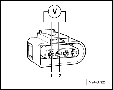
If no voltage is present:

 
N24-0709
  • ‒ Remove wiper arms and cowl panel:

=> Electrical system; Repair group 92; windscreen wiper system; removing and installing windscreen wiper system

  • ‒ → Connect test box V.A.G 1598/22 to control unit wiring harness.
 
A24-0094
  • ‒ → Check wires between test box and 4-pin connector (connector to control unit) for open circuit using current flow diagram.
    Contact 2+socket 13
         Wire resistance: max. 1.5 ω

If the specification is obtained:

  • ‒ Check wire between 4 pin connector contact 1 and fuel pump relay (J17) for open circuit using current flow diagram.
         Wire resistance: max. 1.5 ω

Checking throttle valve control part > < Checking Lambda probe heating before catalyst