
Polo Mk4
| Input shaft - dismantle and assemble |
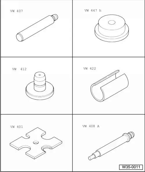
| Special tools and workshop equipment required |
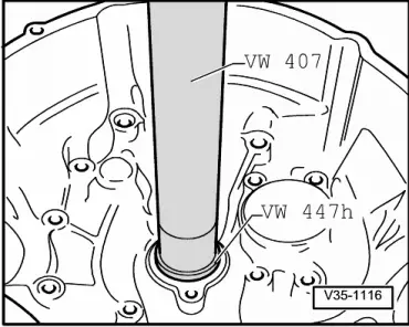
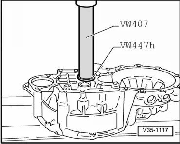
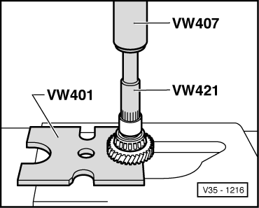
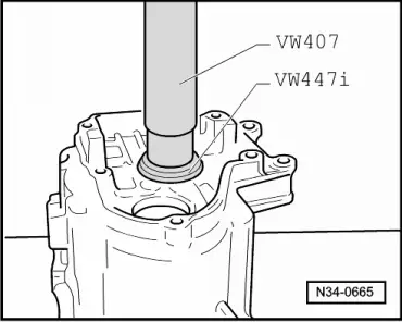
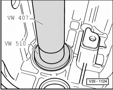
| t | Pressure pin -VW 407- |
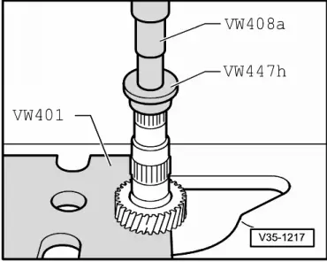
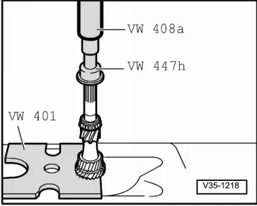
| t | Pressure disc -VW 447 H- |
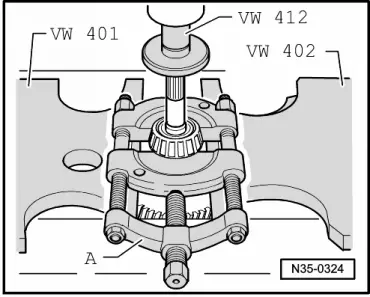
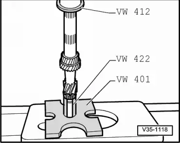
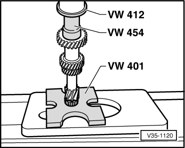
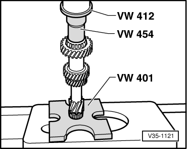
| t | Pressure disc -VW 412- |
| t | Tube -VW 422- |
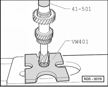
| t | Plate -VW 401- |
| t | Plate -VW 402- |
| t | Pressure pin -VW 408A- |

| t | Tube -VW 421- |
| t | Pressure tube -VW 454- |
| t | Pressure disc -VW 447 i- |
| t | Bracket -VW 540- |
| t | Installation collar -41-501- |
| t | Separating device -KUKKO 17/1- |
 Note
Note
|

| 1 - | Clutch housing |
| 2 - | Outer race/taper roller bearing |
| q | Remove → Fig. |
| q | Install → Fig. |
| 3 - | Taper roller bearing inner race |
| q | Remove → Fig. |
| q | Install → Fig. |
| 4 - | Input shaft |
| q | Adjust → Chapter |
| 5 - | 3rd gear wheel |
| q | Shoulder points to 4th. gear |
| q | Remove → Fig. |
| q | Install → Fig. |
| 6 - | Circlip |
| q | Always renew |
| 7 - | 4th gear wheel |
| q | Pressing off with taper roller bearing outer race and sleeve → Fig. |
| q | Install → Fig. |
| q | Shoulder points to 3rd. gear. |
| 8 - | Taper roller bearing inner race |
| q | Remove with 4th. gear and sleeve → Fig. |
| q | Install → Fig. |
| 9 - | Thrust washer |
| 10 - | Outer race/taper roller bearing |
| q | Remove → Fig. |
| q | Install → Fig. |
| 11 - | Adjustment shim |
| q | Determining thickness: adjusting input shaft → Chapter |
| 12 - | Gearbox housing |
| 13 - | Bushing |
| q | For needle roller bearing. |
| q | Press off with 4th gear wheel and taper roller bearing inner race → Fig. |
| q | Install → Fig. |
| q | Place thrust washer on before installing ( → Item) |
| 14 - | Needle roller bearing |
| 15 - | 5th gear wheel |
| q | Remove together with synchro hub from 5th gear → Chapter |
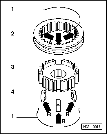
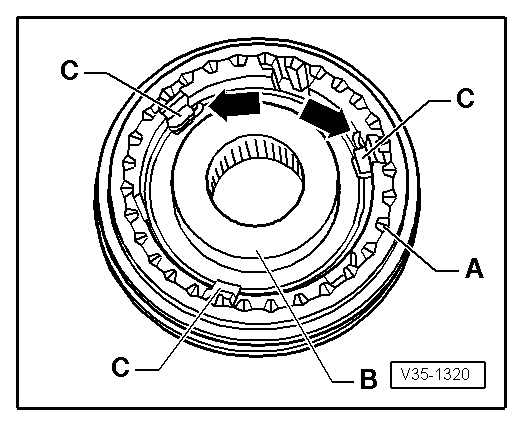
| 16 - | 5nd gear synchro-ring |
| q | With cast locking pieces → Fig. |
| q | Check wear → Fig. |
| 17 - | Spring |
| q | Installation position → Fig. |
| 18 - | Locking pieces (3 units) |
| q | Installation position → Fig. |
| 19 - | Synchro-hub of the 5th gear |
| q | Remove and install → Chapter. |
| 20 - | Locking collar of the 5th gear |
| q | Remove and install → Chapter. |
| 21 - | Spring washer |
| q | Installation position → Fig. |
| 22 - | M10 Torx screw, 80 Nm |
| q | Fitted piece on bolt head locates dished spring → Fig. |
|
|
|
|
|
|
|
|
|
|
|
|
|
|
|
|
|
|
|
|
|
|
|
|
|
|