
Polo Mk4
| Assembly overview |

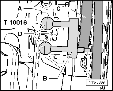
| 1 - | 20 Nm + 1/4 turn (90°) further |
| q | Renew. |
| q | Use camshaft lock -T10016- to loosen and tighten → Fig.. |
| 2 - | Camshaft pulley |
| q | Note position when installing toothed belt → Chapter. |
| 3 - | Seal |
| q | Renew only with camshaft installed. |
| q | Lightly oil sealing lip. |
| q | Renew → Chapter. |
| 4 - | Coupling drive toothed belt |
| q | Mark direction of rotation before removing. |
| q | Check for wear. |
| q | Do not kink. |
| q | Removing, installing and tensioning → Chapter. |
| 5 - | Camshaft housing |
| q | Removing and installing → Chapter. |
| q | Remove sealant remnants. |
| q | Coat with AMV 188 003 A1 before fitting. |
| q | When installing, fit vertically from above onto studs and dowel pins. |
| 6 - | 10 Nm + 1/4 turn (90°) further |
| q | Renew. |
| q | Tighten from inside outwards. |
| 7 - | Sealing cap/ignition transformer retainer |
| 8 - | 10 Nm |
| 9 - | Roller rocker finger |
| q | Check roller bearing. |
| q | Oil contact surface. |
| q | When installing, secure to support element using securing clip. |
| 10 - | Cotters |
| 11 - | Sealing cover |
| 12 - | 20 Nm |
| 13 - | Lifting eye |
| 14 - | Non-return valve, 6 Nm |
| q | Do not overtighten, otherwise the valve can stick. |
| q | Clean thread. Insert with D 154 102 A1. |
| 15 - | Support element |
| q | Check oil spray holes. |
| q | With hydraulic valve clearance compensation. |
| q | Do not interchange. |
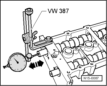
| q | Before installing check camshaft axial clearance → Fig.. |
| q | Oil contact surface. |
| 16 - | Valve spring plate |
| 17 - | Valve spring |
| q | Cylinder head removed: use valve spring tool -3362-. |
| q | Cylinder head installed → Chapter. |
| 18 - | Valve stem seal |
| q | Renew → Chapter. |
| 19 - | Valve guide |
| q | Checking → Chapter. |
| 20 - | 0.3...0.7 bar oil pressure switch -F1-, 25 Nm |
| q | Checking → Chapter. |
| q | If seal is leaking, nip open and renew. |
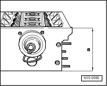
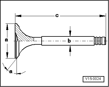
| 21 - | Valves |
| q | Do not rework, only lapping-in is permitted. |
| q | Valve dimensions → Fig.. |
| 22 - | Cylinder head |
| q | Reworking valve seats → Chapter. |
| q | Reworking sealing surface → Fig.. |
| 23 - | 20 Nm |
| 24 - | Tensioning roller |
| q | Checking → Chapter. |
| q | Tensioning toothed belts → Chapter. |
| 25 - | Plug, 45 Nm |
| q | Insert with D 154 102 A1. |
| q | Must not be screwed in too far. |
| q | Maximum permitted insertion depth from top of plug to camshaft housing surface = 2 mm. |
| 26 - | Camshafts |
| q | Checking axial clearance → Fig.. |
| q | Coat with oil before inserting (also axial bearing shoulder). |
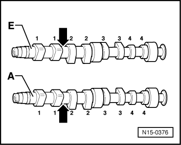
| q | Identification → Fig.. |
| q | After installing, renew oil seal. |
| q | Renewing seals → Chapter. |
| 27 - | O-ring |
| q | Renew. |
| q | Moisten with oil before inserting. |
|
|
|
|
|
|
| Identification between cam pairs | ||
| Engine code | AUA, BBY, BKY | AUB, BBZ |
| Cyl. 1 and 2 | Cyl. 1 and 2 | |
| Inlet shaft -E- | “036AC” | “036AF” |
| Exhaust shaft -A- | “036AA” | “036AG” |
 Note
Note
|
|
| Dimension | Inlet valve | Exhaust valve | |
| Ø a | mm | 29.5 | 26.0 |
| Ø b | mm | 5.973 | 5.953 |
| c | mm | 100.9 | 100.5 |
| α | ∠° | 45 | 45 |