Polo Mk4
 Note
Note
|
 WARNING
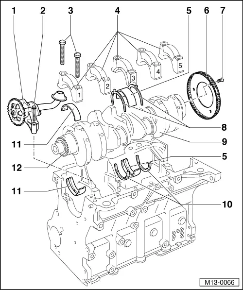
| 1 - | Oil pump |
| q | With 12-bar overpressure valve. |
| q | Before installing, check that both guides for oil pump/crankcase centring are in their positions. |
| q | Remove and install → Chapter. |
| 2 - | 15 Nm |
| 3 - | Gear |
| q | To activate the oil pump. |
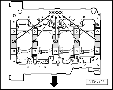
| 4 - | Bearing shells 1, 2, 3, 4 and 5 |
| q | Classification for spare part orders → Fig.. |
| q | For bearing cap without lubrication groove. |
| q | For crankcase with oil groove. |
| q | Do not invert bearing shells already used (identify). |
| 5 - | 65 Nm 90° |
| q | Replace after each removal. |
| q | Tighten to 65 Nm only to measure the radial clearance of the crankshaft. |
| 6 - | Bearing cover |
| q | Bearing cap 1: pulley side. |
| q | Cover of bearing 3 with groove for adjusting rings. |
| q | The shoulders for placing the bearing shells, crankcase/bearing cap must be overlapped. |
| 7 - | Bearing shell 3 |
| q | → Item. |
| q | Do not invert bearing shells already used (identify). |
| 8 - | Speed transmitter |
| q | Replace. |
| q | To Engine speed sensor - G28-. |
| q | The installation is only possible in one position - displaced holes. |
| 9 - | 10 Nm 90° |
| q | Replace after each removal. |
| 10 - | Crankshaft |
| q | Axial clearance (new): 0.07...0.23 mm, Wear limit: 0.30 mm. |
| q | Measure radial clearance with “Plastigage” (new): 0.01...00.04 mm, Wear limit: 0.15 mm. |
| q | Do not rotate the crankshaft when measuring radial gap. |
| q | Crankshaft measures → Chapter. |
| 11 - | Adjustment ring |
| q | For the engine block, bearing 3. |
| q | The writing points to the bearing. |