
Polo Mk4
|
 WARNING
| 1 - | Piston rings |
| q | Displace the opening by 120°. |
| q | Remove and install with ring pliers. |
| q | Reference “TOP” pointing towards the piston head. |
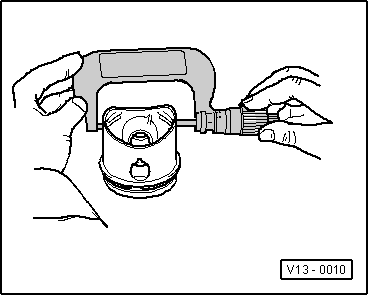
| q | Check opening between ends. → Fig. |
| q | Check ring clearance in the piston channel. → Fig. |
| 2 - | Piston |
| q | Check → Fig. |
| q | Mark correspondence with the cylinder. |
| q | The arrow on piston head points to the pulley side. |
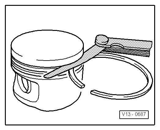
| q | Install with the ring tensioning strap. |
| 3 - | Piston pin |
| q | In case of difficulties in the removal, heat the piston to 60° C. |
| q | Remove and install by using the Puller and Fitter - VW 222A-. |
| 4 - | Retaining ring |
| q | Replace. |
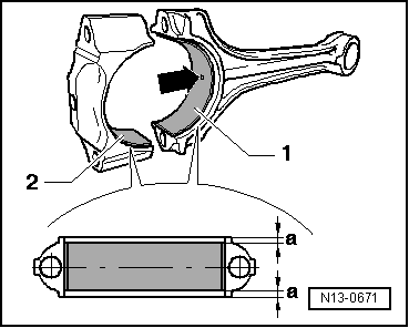
| 5 - | Connecting rod |
| q | With splitting (breaking) → Fig. |
| q | Only replace by complete set. |
| q | Mark correspondence with cylinder -B-. |
| q | Installation position: Markings -A- point towards the pulley side. |
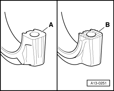
| 6 - | Bearing shell |
| q | Check the installation position → Fig. |
| q | Place bearing shells centered. |
| q | Do not invert bearing shells already used. |
| q | Ensure it is firmly fastened. |
| q | Clearance in the groove (new): 0.10...00.35 mm, Wear limit: 0.40 mm. |
| q | Measure radial clearance with “Plastigage” (new): 0.01...00.05 mm, Wear limit: 0.09 mm. Do not rotate the crankshaft when measuring radial gap. |
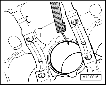
| 7 - | Engine block |
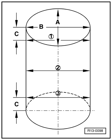
| q | Check cylinder diameter → Fig. |
| q | Measures of the pistons and cylinders → Chapter. |
| 8 - | Connecting rod cap |
| q | Pay attention on the installation position. |
| q | Due to splitting (breaking) of the connecting rods, the cap only seats in one position and with the corresponding connecting rod. |
| 9 - | 30 Nm 90° |
| q | Replace after each removal. |
| q | Lubricate the thread and the contact surface with oil. |
| q | To measure the radial clearance, tighten to 30 Nm only, without angular torque. |
|
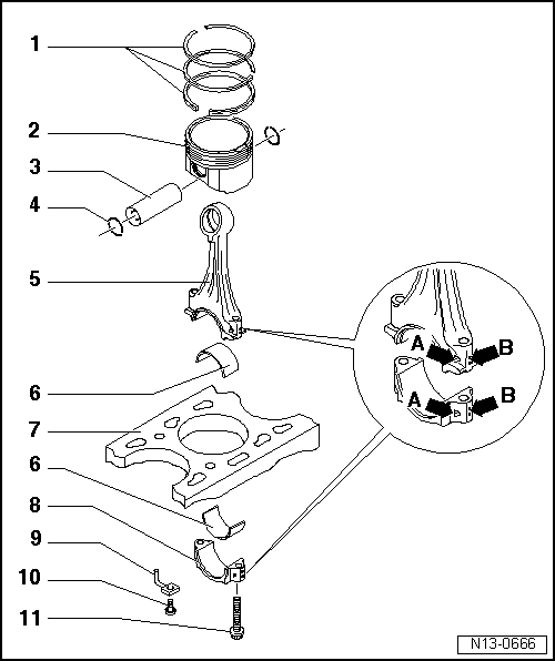
| 1 - | Segment rings |
| q | Displace the opening by 120°. |
| q | Remove and install with ring pliers. |
| q | Reference “TOP” pointing towards the piston head. |
| q | Check opening between ends → Fig. |
| q | Check ring clearance in the piston channel → Fig. |
| 2 - | Piston |
| q | Check → Fig. |
| q | Mark correspondence with the cylinder. |
| q | The arrow on piston head points to the pulley side. |
| q | Install with the ring tensioning strap. |
| 3 - | Piston pin |
| q | In case of difficulties in the removal, heat the piston to 60°C. |
| q | Remove and install by using the Puller and Fitter - VW 222A-. |
| 4 - | Piston pin retaining ring |
| q | Replace. |
| 5 - | Connecting rod |
| q | With broken cap. |
| q | Only replace by complete set. |
| q | Mark correspondence with cylinder -B-. |
| q | Installation position: marks -A- point towards pulley side. |
| 6 - | Bearing shell |
| q | Pay attention to the assembly position. |
| q | Place bearing shells centered. |
| q | Do not invert bearing shells already used if they are going to be used again. |
| q | Check firm seating. |
| q | New axial clearance: 0.05...00.31 mm. Wear limit: 0.37 mm |
| q | Measure radial clearance with “Plastigage”: new: 0.01...00.05 mm. Wear limit: 0.09 mm. Do not rotate the crankshaft when measuring radial gap. |
| 7 - | Engine block |
| q | Check cylinder diameter → Fig. |
| q | Measures of the pistons and cylinders → Chapter. |
| 8 - | Connecting rod cap |
| q | Pay attention to the assembly position. |
| q | Due to splitting (breaking) of the connecting rods, the cap only seats in one position and fits only on the connecting rod to which it belongs. |
| 9 - | Oil injector |
| q | For piston cooling. |
| 10 - | Valve, 27 Nm |
| q | Opening pressure: 1.3...1.6 bar. |
| 11 - | 30 Nm 90° |
| q | Torx E 10. |
| q | Replace after each removal. |
| q | Lubricate the thread and supporting surface. |
| q | To measure the radial clearance, tighten to 30 Nm, without the angular torque. |
|
|
| Piston ring | Opening between ends | ||
| new | Wear limit | ||
| Compression rings | mm | 0,20...0,40 | 0,80 |
| Oil scraper ring | mm | 0,25...0,50 | 0,80 |
|
|
| Piston ring | Groove clearance | ||
| new | Wear limit | ||
| Compression rings | mm | 0,06...0,09 | 0,20 |
| Oil scraper ring | mm | 0,03...0,06 | 0,15 |
|
|
|
|
 Note
Note
|
|