
Polo Mk4
 WARNING
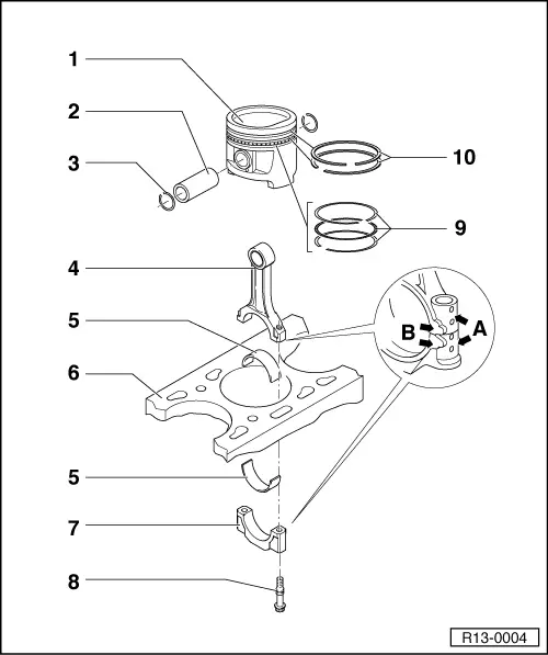
| 1 - | Piston |
| q | Check → Fig. |
| q | Mark assembly position and correspondence with the cylinder. |
| q | Arrow on piston upper part points to the pulley side. |
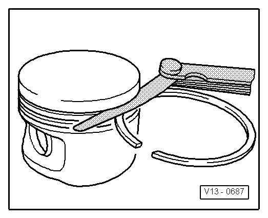
| q | Install with ring compressor. |
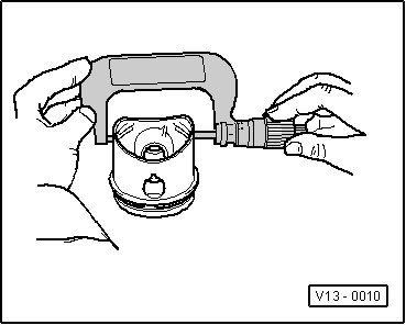
| 2 - | Piston pin |
| q | In case of difficulties in the removal, heat the piston to 60°C. |
| q | Remove and install with Pin or VW 010-206 -10-206-. |
| 3 - | Piston pin retaining ring |
| q | Replace. |
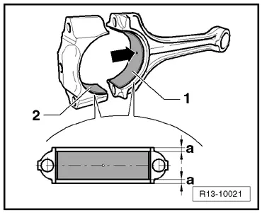
| 4 - | Conrod |
| q | Replace in pairs only. |
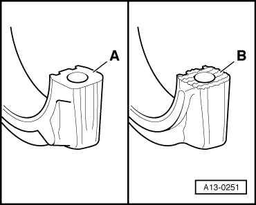
| q | Mark corresponding position relative to cylinder -A-. |
| q | Assembly position: marks -B- point to the flywheel side. |
| q | On conrods without marks -B-, the installation position is the painted faces (conrod and cap), facing the crankcase venting device side. |
| q | Besides defining the pair (conrod and cap), colors painted on conrods and caps also define the position (conrod in cap). |
| q | Piston/conrod axial clearance; 0.20...0.40 mm wear limit 0.50 mm. |
| q | It is separated from cap by the breakage process → Fig. |
| 5 - | Bearing shell |
| q | Check assembly position. |
| q | Do not mix used bearing shells in case they are reused, mark. |
| q | Install bearing shells centrally. |
| q | Measure radial clearance using Plastigage: new: 0.020...0.061 mm wear limit: 0.004 in. Do not rotate crankshaft while measuring radial clearance. |
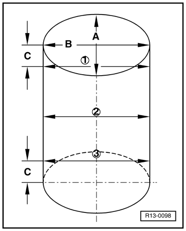
| 6 - | Cylinder block |
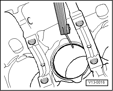
| q | Check cylinder bore → Fig. |
| q | Piston and cylinder dimensions → Chapter. |
| 7 - | Conrod cap |
| q | Check assembly position. |
| q | Due to the rupture process applied to the conrods, the cap can be assembled in only one position and only on the respective conrod. |
| q | Besides defining the pair (cap and conrod), colors painted on caps and conrods also define the position (cap in conrod). |
| q | It is separated from body by the breakage process → Fig. |
| 8 - | 30 Nm + 90° |
| q | Replace after each removal. |
| q | Lubricate threads and stop surfaces. |
| q | Tighten to 30 Nm to measure radial clearance, but do not apply the angular torque. |
| 9 - | Oil scraper rings |
| q | Remove and install manually and carefully the 3-part oil scraper rings. |
| q | „TOP“ mark must point towards piston crown. |
| q | Check opening between ends → Fig. |
| q | Check ring clearance in the piston groove → Fig. |
| 10 - | Compression rings |
| q | Move openings 120°. |
| q | Remove and install compression rings with compression ring pliers. |
| q | „TOP“ mark points towards the piston crown. |
| q | Check opening between ring ends → Fig. |
| q | Check ring clearance in the piston groove → Fig. |
|
|
|
|
| Piston ring | Wear limit |
| 1. Compression ring | 0.04 in |
| 2. Compression ring | 0.04 in |
| Oil scraper ring | 0.04 in |
|
| Ring | Opening between ends | ||
| new | wear limit | ||
| 1st compression ring | mm | 0,20...0,35 | 1,0 |
| 2nd compression ring | mm | 0,20...0,40 | 1,0 |
| Oil scraper ring | mm | 0,25...0,75 | 1,0 |
|
|
| Piston ring | Wear limit |
| 1. Compression ring | 0.01 in |
| 2. Compression ring | 0.01 in |
| Oil scraper ring | 0.01 in |
|
| Ring | Groove clearance | |||
| new (with Mahle piston) | new (with Federal Mogul piston) | wear limit | ||
| 1st compression ring | mm | 0,030...0,080 | 0,040...0,080 | 0,15 |
| 2nd compression ring | mm | 0,020...0,060 | 0,020...0,060 | 0,15 |
| Oil scraper ring | mm | 0,010...0,150 | 0,010...0,150 | 0,20 |
|
|
 Note
Note
|
|
Note
|
|