
Polo Mk4
| Gear components |
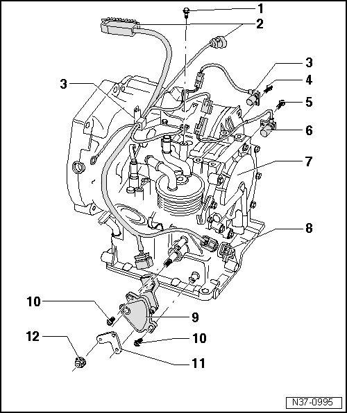
| 1 - | Screw, 6 Nm |
| q | To support the harness |
| 2 - | Harness |
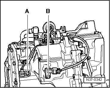
| 3 - | Transmitter of gear speed -G68- |
| q | Connector in the transmitter |
| q | Location, disassembly and assembly → Fig. |
| 4 - | Screw, 6 Nm |
| 5 - | Screw, 6 Nm |
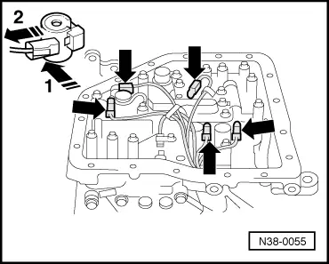
| 6 - | Transmitter of transmission regime -G38- |
| q | With connection cable |
| q | Location, disassembly and assembly → Fig. |
| 7 - | Gearbox |
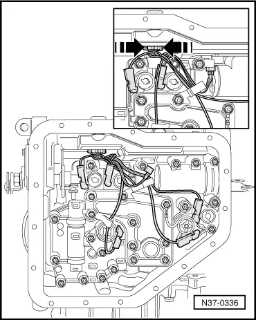
| 8 - | Harness |
| q | For electric valves and the transmission oil temperature transmitter (ATF) -G93- |
| q | Location, disassembly and assembly → Anchor |
| 9 - | Multifunction switch -F125- |
| q | Adjust → Fig. |
| 10 - | Screw with collar |
| q | Tightening torque → Fig. |
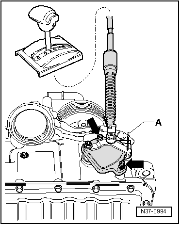
| 11 - | Connecting rod |
| q | For selector axle |
| 12 - | Nut, 17 Nm |
|
|
|
|
|
|