| –
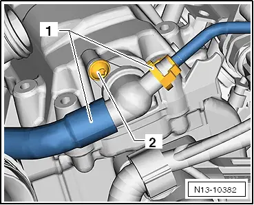
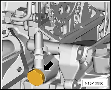
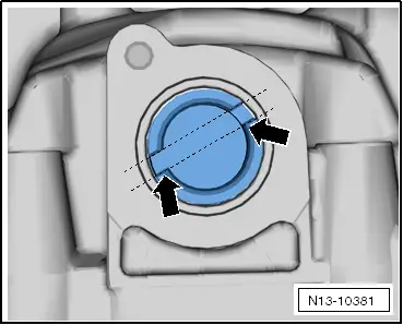
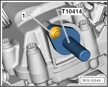
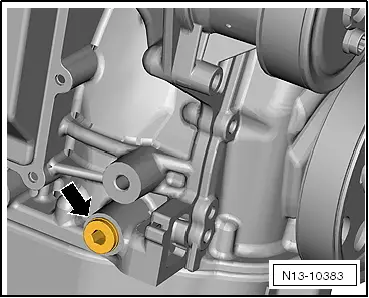
| Unscrew plug -arrow- from cylinder block. |
| –
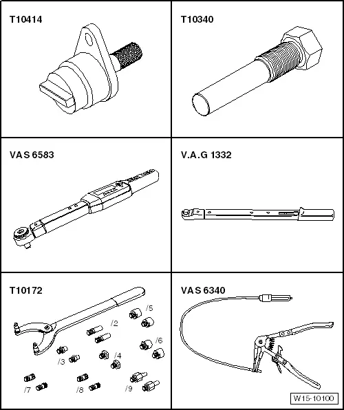
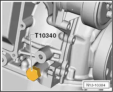
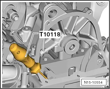
| Screw locking pin -T10340- to stop into crankcase. |
| –
| Turn crankshaft in normal direction of rotation until the stop. |

Caution | If locking pin -T10340- cannot be screwed in as far as stop, this indicates that crankshaft is not in the correct position! |
| In this case, proceed as described below. |
|
| –
| Turn crankshaft 1/4 revolution (90°) in normal direction of rotation. |
| –
| Screw locking pin -T10340- to stop into crankcase. |
| –
| Tighten locking pin -T10340- to 30 Nm. |
| –
| Turn crankshaft in normal direction of rotation until the stop. |
|
|
|

 Note
Note