
Polo Mk5
| Removing and installing bonded rubber bush |

| Special tools and workshop equipment required |
| t | Thrust piece -3416/1- |
| t | Thrust piece -3416/2- |
| t | Assembly tool -T10205- |
| t | Assembly tool -T10254- |
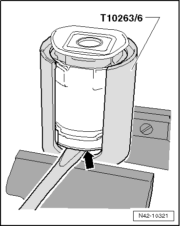
| t | Assembly tool -T10263- |
| t | Torque wrench -V.A.G 1332- |

| t | Engine and gearbox jack -V.A.G 1383 A- with universal gearbox support -V.A.G 1359/2- |
| t | Brake pedal depressor -V.A.G 1869/2- |
| t | Hydraulic press -VAS 6178- |
| t | Foot pump -VAS 6179- |
|
|
|
|
|
|
|
|
|
|
|
|
|
|
|
|
|
 Note
Note
|
|
|
|
|
|
|
|
|
|
| Specified torques |
| Component | Specified torque | ||||
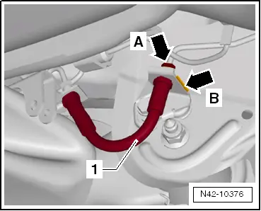
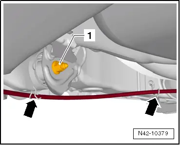
Rear axle to mounting bracket
| 45 Nm + 90° | ||||
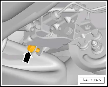
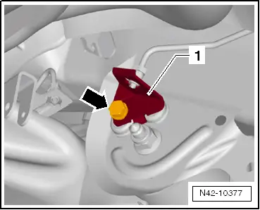
| Rear left vehicle level sender -G76- to axle body | 15 Nm | ||||
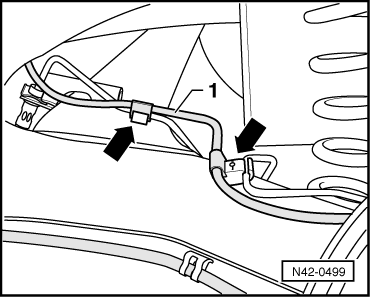
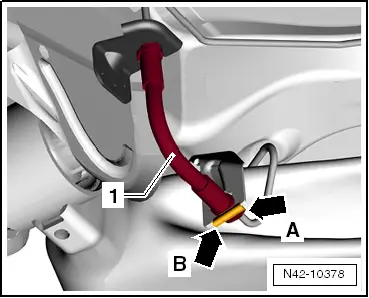
| Retainer for left brake line | 20 Nm | ||||
| Brake lines to brake hose | 14 Nm |