
Up!
| Assembly overview |
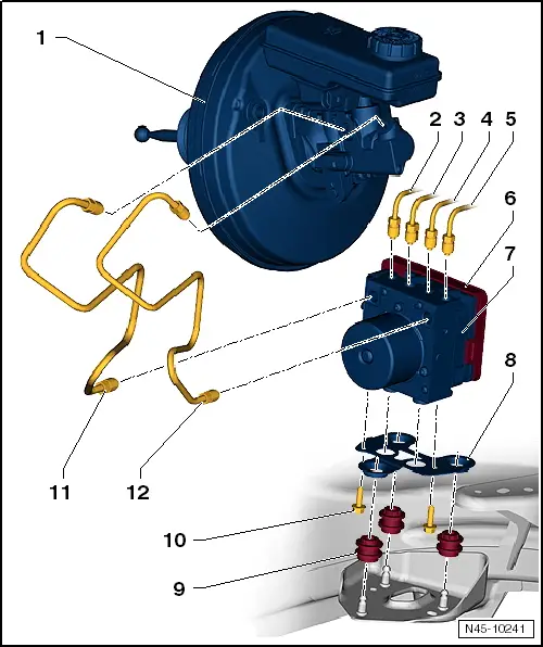
| 1 - | Brake servo |
| q | Removing and installing → Chapter. |
| 2 - | Brake line, 14 Nm |
| q | To front right brake caliper. |
| q | Marked on hydraulic unit with -VR-. |
| q | With thread M10 x 1 |
| 3 - | Brake line, 14 Nm |
| q | To rear left wheel brake cylinder |
| q | Marked on hydraulic unit with -HL-. |
| q | With thread M12 x 1 |
| 4 - | Brake line, 14 Nm |
| q | To rear right wheel brake cylinder |
| q | Marked on hydraulic unit with -HR-. |
| q | With thread M10 x 1 |
| 5 - | Brake line, 14 Nm |
| q | To front left brake caliper. |
| q | Marked on hydraulic unit with -VL-. |
| q | With thread M12 x 1 |
| 6 - | ABS control unit -J104- |
| q | Removing and installing ABS hydraulic unit -N55- with ABS control unit -J104- → Chapter. |
| 7 - | ABS hydraulic unit -N55- |
| q | ABS return flow pump -V39- and valve block should not be separated from each other |
| q | When renewing the hydraulic unit, always seal the old part with plugs from repair kit -1H0 698 311 A-. |
| q | Removing and installing ABS hydraulic unit -N55- with ABS control unit -J104- → Chapter. |
| 8 - | Bracket |
| q | Allocation → Electronic parts catalogue „ETKA“ |
| 9 - | Rubber damper |
| 10 - | Hexagon bolt, 8 Nm |
| 11 - | Brake line, 14 Nm |
| q | From primary piston circuit of brake master cylinder to hydraulic unit. |
| q | Marked on hydraulic unit with -HZ2-. |
| q | With thread M12 x 1 |
| 12 - | Brake line, 14 Nm |
| q | From secondary piston circuit of brake master cylinder to hydraulic unit. |
| q | Marked on hydraulic unit with -HZ1-. |
| q | With thread M12 x 1 |