volkswagen Workshop Repair Guides

Volkswagen Workshop Service and Repair Manuals

Multi-pin connector pin assignment on rear of control and display unit > < Overview - control and display unit
Removing and installing control and display unit
Special tools and workshop equipment required
   
t  Removal wedge -3409-
Removing
  W00-0016
–  Remove slide control for fresh air/recirculated air -1- in -direction of arrow-.
  N87-10902
–  Unclip trim -1- at marked points -arrows- using removal wedge -3409- and remove trim -1-.
  N87-10899
–  Unscrew bolts -1- (1.5 Nm).
–  Remove radio → Communication; Rep. gr.91 or centre trim → General body repairs, interior; Rep. gr.70.
  N87-10900
–  Unhook control and display unit -1- in -direction of arrow- from mountings -arrows A- and pull it out frontwards.
–  Disconnect connectors from control and display unit -1-.
  N87-10901
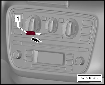
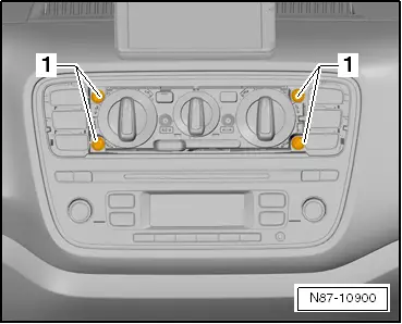
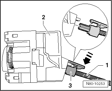
–  Detach flexible shafts -1- for defroster and air distribution flap and temperature flap as well as fresh air/recirculated air flap cable from control and display unit -2-.
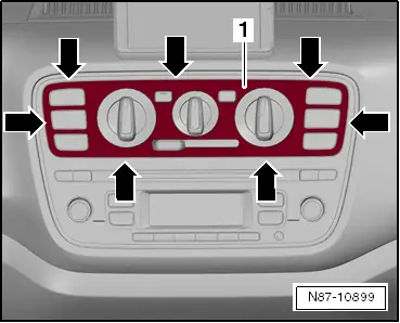
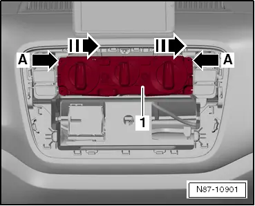
–  Remove control and display unit.
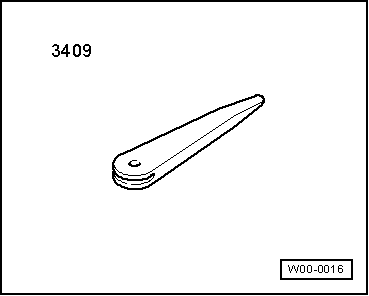
  Note
The flexible shaft connexion -3- is referred to as „terminal“.
Installing
–  Installation is carried out in the reverse order. When installing, note the following:
t  Always install slide control for fresh air/recirculated air with plug-in socket pointing upwards.
  Note
When the flexible shafts are installed, the actuators and rotary knobs on the heated air and fresh air controls must be positioned correctly relative to each other, or the system will malfunction.
  N80-10253

Multi-pin connector pin assignment on rear of control and display unit > < Overview - control and display unit