
Up!
| Assembly overview - drive shaft |
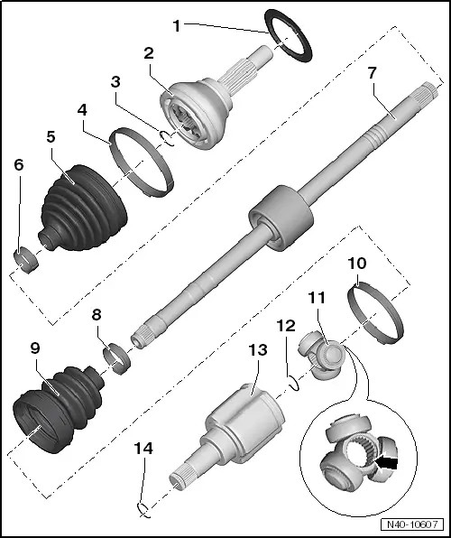
| 1 - | Deflector ring |
| q | Ensure deflector ring is seated correctly before installing drive shaft → Anchor. |
| 2 - | Outer constant velocity joint |
| q | Renew only as complete unit |
| q | Removing → Anchor. |
| q | Installing: drive onto shaft with plastic hammer until compressed circlip seats |
| q | Checking → Chapter |
| 3 - | Retaining ring |
| q | Insert in groove in shaft |
| 4 - | Clamp |
| q | Always renew after removing. |
| q | Various versions |
| q | Allocation → Electronic parts catalogue „ETKA“ |
| q | Tightening → Fig. |
| 5 - | Boot for constant velocity joint |
| q | Check for splits and chafing |
| q | Material: Hytrel (polyester elastomer) |
| q | Coat sealing surface of constant velocity joint with -D 454 300 A2- before installing. |
| 6 - | Clamp |
| q | Always renew after removing. |
| q | Tightening → Fig. |
| 7 - | Drive shaft |
| 8 - | Clamp |
| q | Always renew after removing. |
| q | Tightening → Fig. |
| 9 - | Boot for triple roller joint |
| q | Check for splits and chafing |
| 10 - | Clamp |
| q | Always renew after removing. |
| q | Tightening → Fig. |
| 11 - | Triple roller star with rollers |
| The chamfer -arrow- points towards drive shaft splines. |
| 12 - | Retaining ring |
| q | Always renew after removing. |
| 13 - | Joint body |
| 14 - | Retaining ring |
| q | Insert in groove in joint body. |