volkswagen Workshop Repair Guides

Volkswagen Workshop Service and Repair Manuals

Wheel bearing > < Checking swivel joint
Removing and installing swivel joint
   
Removing and installing swivel joint
Special tools and workshop equipment required
t  Ball joint puller -3287A-
t  Torque wrench -V.A.G 1332-
t  Engine and gearbox jack -V.A.G 1383 A-
t  Angle wrench -V.A.G 1756-

   
t  Remover -3283 A-
Carry out the following work:
Removing
–  Lift vehicle far enough to take weight off front axle.
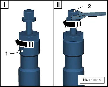
–  Loosen twelve-point nut for drive shaft.
  Caution
Wheel bearings must not be subjected to load after bolt securing drive shaft to wheel hub has been loosened.
If wheel bearings are loaded with weight of vehicle, wheel bearings will be damaged and service life of wheel bearings will be considerably reduced.
It is not permissible to turn drive shaft bolt more than 90° anti-clockwise if vehicle is standing on its wheels.
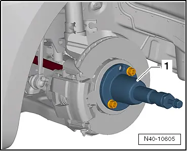
Do not attempt to move the vehicle without the drive shafts fitted as this would damage the wheel bearing. If a vehicle nevertheless has to be moved, comply with the following:
t  
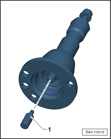
Install an outer joint instead of the drive shaft.
t  Tighten outer joint to 120 Nm.
–  Loosen wheel bolts.
–  Raise vehicle.
–  Remove wheel.
  W00-10981
–  Remove nuts -arrows-.
–  Pull swivel joint out of suspension link.
–  Bend suspension link downwards as far as necessary.
–  Pull drive shaft completely out of wheel hub.
If the drive shaft cannot be pulled out of the wheel bearing by hand, use press tool -3283 A-.
  N40-10350
Before using press tool -3283 A- ensure that thrust piece -1- is inserted.
  N40-10618
Using press tool -3283 A-:
–  Secure press tool -3283 A--1- with two wheel bolts to wheel hub.
  N40-10605
–  It is essential to follow specified sequence.
I - Tighten knurled nut -1- hand-tight.
II - Only turn press tool -3283 A- by means of bolt -2- using a spanner in order to press out drive shaft.
  Note
At the end of the procedure or for pressing out drive shaft further the spindle must be moved to its original position in order to deploy the hydraulic force!
–  Secure drive shaft to body.
  Note
Place engine and gearbox jack -V.A.G 1383 A- or similar underneath (danger of accident through falling parts when pressing out the swivel joint).
  N40-10619
–  Loosen nut for swivel joint.
  Caution
Leave nut screwed on a few turns to protect thread on pin.
–  Apply ball joint splitter -3287 A- as shown in figure and press out swivel joint.
Installing
  N40-10351
Observe installation position of swivel joints!
Left swivel joint
Arrow with marking „L4“ to the direction of travel
  N40-10348
Right swivel joint
Arrow with marking „R4“ to the direction of travel
Observe exact installation position of swivel joints!
Caster will be incorrect if swivel joints are not installed in correct position.
–  Fit swivel joint in wheel bearing housing.
–  Screw on new self-locking nut and counterhold at swivel joint with -T40- Torx key.
–  Fit drive shaft in wheel hub.
  N40-10349
Make sure that deflector ring -1- is clipped completely onto outer joint.
  Note
t  The lugs of deflector ring -1- must face towards outer joint.
t  Deflector ring -1- must lie on contact surface of outer joint -arrow-.
  Note
  N40-10617
If deflector ring -1- is not positioned correctly or if it fell off outer joint, it must be driven onto outer joint to stop using thrust piece -T10049-.
  N40-10616
–  Tighten nuts -arrows-.
  Note
Ensure that bellows are not damaged or twisted.
–  Install wheel and tighten bolts or nuts → Chapter.
–  Lightly coat thread and splines of stub axle and contact surfaces of wheel hub/twelve-point nut with pressure-resistant oil Fuchs Renolin B15 VG46.
–  Tighten twelve-point nut for drive shaft.
  N40-10391
Specified torques
ComponentSpecified torque
Swivel joint to wheel bearing housing
t  Use new nuts.
60 Nm
Swivel joint to suspension link
t  Use new bolts.
100 Nm
12-point nut on drive shaft
t  Use new nuts.
50 Nm + 45° further


Wheel bearing > < Checking swivel joint