
Up!
| Renewing wheel bearing |

| Special tools and workshop equipment required |
| t | Thrust piece -3002- |
| t | Assembly tool -T10064- |
| t | Assembly tool -T10205- |
| t | Torque wrench -V.A.G 1331- |
| t | Torque wrench -V.A.G 1332- |
| t | Engine and gearbox jack -V.A.G 1383 A- |

| t | Torque wrench -V.A.G 1410- |
| t | Thrust piece -V.A.G 1459B-6- from hydraulic wheel bearing tool -V.A.G 1459B- |
| t | Thrust sleeve -V.A.G 1459B/2-8- from supplementary set -V.A.G 1459B/2- |
| t | Hydraulic press -VAS 6178- |
| t | Foot pump -VAS 6179- |
| t | -2-Puller -Kukko 18/0-. |
| t | -3-Separator -Kukko 17/1- |
|
|
|
|
 Caution
|
|
|
|
|
|
|
|
 Note
Note
Note
|
|
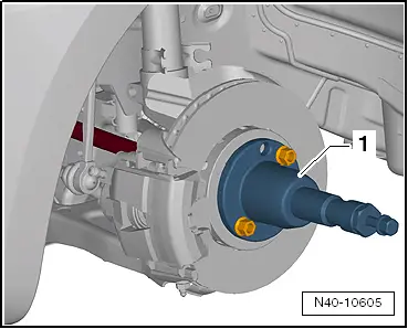
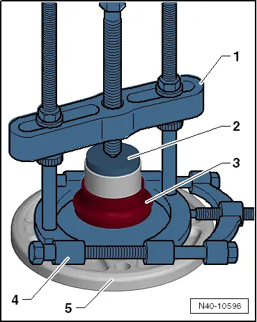
| Press out wheel hub |

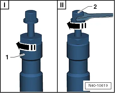
| – | Fit gripping pieces -T10064/6A--1- to wheel hub. |
| – | Screw wheel bolt -2- into wheel hub and secure lower gripping piece -T10064/6A-. |
| – | Install tools as shown in illustration and preload hydraulic press -VAS 6178-. |
Note| It must be ensured that the wheel bolt -arrow- and bridge -8- are offset. |
| 1 - Gripping pieces -T10064/6A- |
| 2 - Wheel bolt |
| 3 - Tube -T10064/1- |
| 4 - Thrust plate -T10205/1- |
| 5 - Hydraulic press -VAS 6178- and thrust piece -T10205/13- |
| 6 - Nut -T10205/8-2- |
| 7 - Spindle -T10205/8-1- |
| 8 - Bridge on tube -T10064/1- |
| – | Hold appliance firmly and press out wheel hub. |
|
|
| Pressing out wheel bearing |

| 1 - Spindle -T10205/8-1- |
| 2 - Nut -T10205/8-2- |
| 3 - Thrust piece -V.A.G 1459B-6- |
| 4 - Thrust sleeve -V.A.G 1459B/2-8- |
| 5 - Thrust plate -T10205/1- |
| 6 - Hydraulic press -VAS 6178- and thrust piece -T10205/13- |
| 7 - Nut -T10205/8-2- |
| – | Hold appliance firmly and press out wheel bearing. |
|
|
|
|
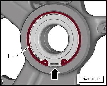
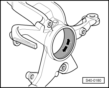
| Pressing in wheel bearing |
| Make sure it is installed in correct position: |
| The black ring of wheel bearing must face towards wheel bearing housing (inside of vehicle). |

| 1 - Nut -T10205/8-2- |
| 2 - Thrust piece -T10064/4-, with large diameter facing towards wheel bearing housing |
| 3 - Wheel bearing |
| 4 - Thrust piece -T10064/2- |
| 5 - Thrust plate -T10205/1- |
| 6 - Hydraulic press -VAS 6178- and thrust piece -T10205/13- |
| 7 - Nut -T10205/8-2- |
| 1 - Spindle -T10205/8-1- |
| – | Press in wheel bearing to stop. |
| Do not cant wheel bearing when pressing it in. |
Note
|
|
| Pressing in wheel hub |

| 1 - Spindle -T10205/8-1- |
| 2 - Nut -T10205/8-2- |
| 3 - Thrust piece -V.A.G 1459B-6- |
| 4 - Wheel hub |
| 5 - Thrust plate -T10205/1- |
| 6 - Hydraulic press -VAS 6178- and thrust piece -T10205/13- |
| 7 - Nut -T10205/8-2- |
| Press in wheel hub to stop. |
Note
Note |
|
|
|
Note
|
|
| Specified torques |
| Component | Specified torque | ||
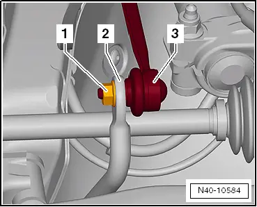
Swivel joint to suspension link
| 100 Nm | ||
| Coupling rod to anti-roll bar | 40 Nm | ||
12-point nut on drive shaft
| 50 Nm + 45° further |