
240 L4-2320cc 2.3L SOHC VIN 83 B230FD (1993)
1.
Remove steering rack assembly from vehicle, then using tool No. 5046, mount unit in vise.
2.
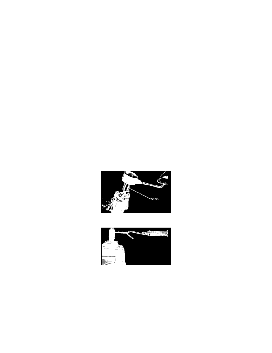
Loosen both side rubber bellows and drain oil, Fig. 6.
3.
Loosen locknut, unscrew and remove left ball stud, locknut and bellow.
4.
Unstake and unscrew steering rod.
5.
Remove oil pipes.
6.
Remove cover for pre-tensioning device. Remove pre-tensioning piston, O-ring and spring.
7.
Remove pinion housing dust shield from pinion shaft.
8.
Remove pinion housing cover, seal and O-ring.
9.
Remove pinion, upper roller bearing, lower washer and thrust bearing.
10.
Scribe marks on center tube and housing for installation.
11.
Using tool No. 5178, loosen locking collar next to pinion housing, then place right side housing in vise and remove lock collar and center tube.
12.
Remove O-rings from center tube.
13.
Remove rack and spacer tube as a unit.
14.
Remove washer from right side of pinion housing.
15.
Using tool No. 1819, remove seal from pinion housing.
16.
Using a suitable punch, remove needle bearing from inside of housing. Bearing should only be removed if it requires replacement.
17.
Remove lock rings, thrust washers and piston from rack. Fill lock ring grooves with grease and slide tube away from rack teeth.
18.
Using tool No. 1819, remove inner tube seal and narrow brass bushing.
19.
Remove O-ring and washer from spacer tube.
20.
Remove star washer, bearings and seal from right side housing.
21.
Remove seal and O-ring from pinion housing cover.
22.
Remove O-ring and depressor from pre-tension piston.
23.
Remove rings from pinion valve unit.
ASSEMBLY
1.
Clean all parts and inspect for wear and damage, replace as necessary. Valve housing should not be disassembled. Replace if defective.
2.
Lubricate needle bearing using suitable lubricant. Using a suitable drift, install needle bearing. Bearing bottom should be flush with housing. If
bearing is set too far, pinion preload will be affected.
3.
Install lower washers and thrust bearing.
4.
Install pinion assembly, roller bearing and pinion housing cover.
Fig. 5 Checking Pinion Torque. 240 Series w/power Steering (ZF Gear Use Tool No. 5179)
Fig. 7 Checking Bearing Preload (typical)
5.
Adjust pinion using one of the following methods:
a. Using adapter No. 5179 and torque wrench, check torque of pinion, Fig. 5. Torque should be 1.3-2.2 inch lbs.
b. Using suitable spring gauge, check pinion torque, Fig. 7. Scale should read 3.7-6.5 lbs.
c. Preload is adjusted by altering the bearing washer under the cover. Washers are available in various sizes.
6.
Remove pinion assembly, bearings and spacers.
7.
Install all rings on valve body grooves.
8.
Install seal and spacer ring in pinion housing.
9.
Install bronze bushing in spacer tube, chamfered side down.
10.
Install spacer tube seal in spacer tube.
11.
Install O-ring and washer on spacer tube.
12.
Install seal, bearings and star washer in right side housing.
13.
Fill lock ring grooves and coat surrounding area with suitable grease, then slide spacer tube into steering rack from smooth end and pass it quickly