
940 L4-2.3L SOHC VIN 88 B230F (1992)
Manifold Pressure/Vacuum Sensor: Testing and Inspection
TESTING PROCEDURE:
NOTE: While trouble shooting, always check the wiring, fuses and connectors for good condition and routing. Use the wiring diagrams found in
CHASSIS ELECTRICAL DIAGRAMS to supplement your testing efforts.
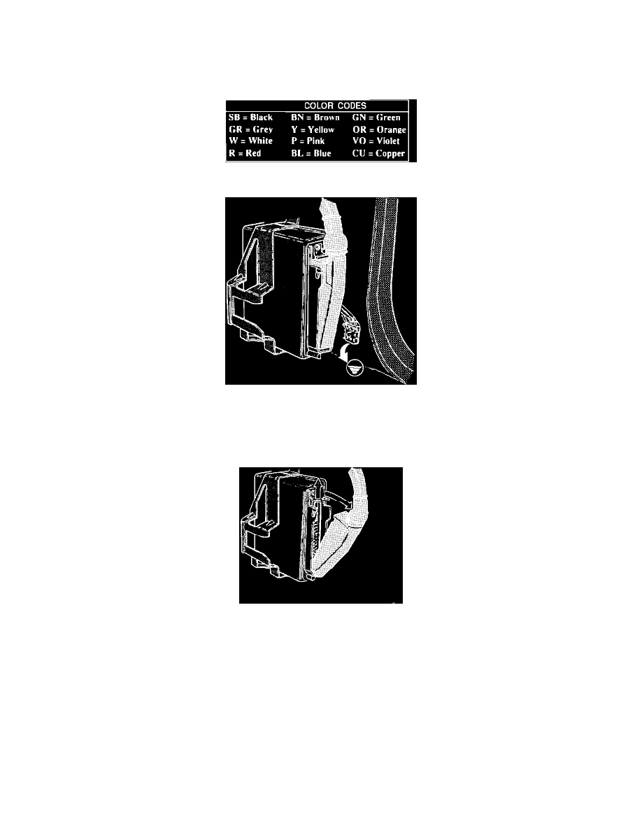
Color Code Legend
Checking ECU Ground Connections
1.
Turn ignition OFF.
2.
Access fuel injection ECU by removing the passenger side kick panel and glove compartment.
3.
Check fuel injection ECU ground connections. They should make good contact and fit tight.
Removing ECU Connector
4.
Remove fuse #1 (located in central electric unit behind ash tray) to interrupt the power supply. Then remove the ECU connector by pressing up the
latch and folding out the wire cluster.