
940 SE L4-2320cc 2.3L SOHC Turbo VIN 87 B230FT (1991)
Ignition Control Module: Testing and Inspection
TESTING PROCEDURE:
NOTE: While trouble shooting, always check the wiring, fuses and connectors for good condition and routing. Use the wiring diagrams found in
CHASSIS ELECTRICAL DIAGRAMS to supplement your testing efforts.
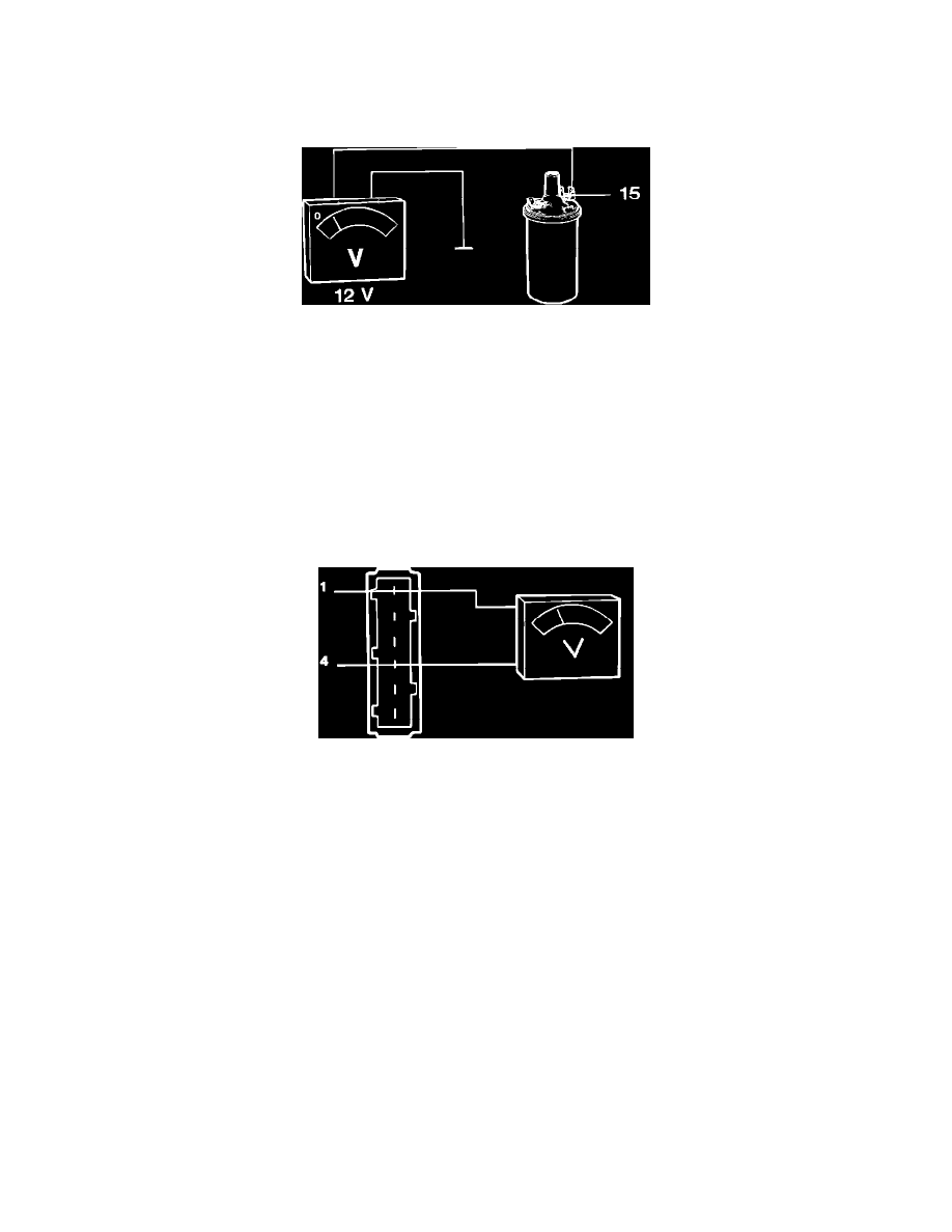
Checking Supply At Ignition Coil
1.
Turn ignition ON.
2.
Measure voltage between ignition coil terminal 15 (blue) and ground.
Reading: approx. 12 volts
If not, check wire and connectors from terminal 15 to suppressor relay (located on driver side fenderwell). Repair as needed. If wiring is O.K.,
check suppressor relay (see SUPPRESSOR RELAY).
3.
Turn ignition OFF.
4.
Disconnect the power stage connector.
IMPORTANT:Ignition must be OFF when connecting or disconnecting power stage connector.
5.
Remove rubber boot from connector to uncover pins. Always test the pins from the back. Never test pins from the front, damage may occur.
Checking Terminals #1 And 4 At Power Stage
6.
Turn ignition ON.
7.
Measure voltage between power stage terminal 1 and ground.
Reading: approx. 12 volts
If not, check wire and connectors from power stage terminal 1 to ignition coil terminal 1. Repair as needed. If no fault can be found, proceed with
next steps.
8.
Measure voltage between power stage terminal 4 and ground.
Reading: approx. 12 volts
If not, check wire and connectors from terminal 4 ignition switch. Repair as needed.
9.
Turn ignition OFF.