
C70 L5-2.4L Turbo VIN 63 B5244T7 (2003)
-
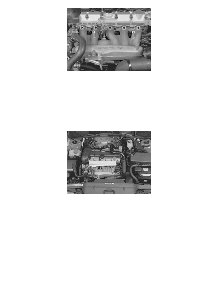
a new gasket held in position by the lower screws for the intake manifold.
-
the intake manifold.
Do not forget the crankcase ventilation hose. The hose must be inserted up through the gap between the second and third ducts.
-
position the delivery line between the first and second duct.
-
the three upper screws.
Tighten all screws starting from the center. Tighten to 20 Nm.
Finishing
Install
-
the fuel rail.
-
Press together the quick-release connector.
-
Use new screws.
-
Tighten to 10 Nm.
-
the connectors for the injectors and the cover plate.
-
the vacuum hoses according to the earlier markings.
-
the plastic charge air pipe and the hose to the charge air cooler (CAC).
-
the connectors for the sensors in the plastic charge air pipe.
-
the air baffle from the control module box at the engine cooling fan (FC).
-
the dip stick in the intake manifold.
Final Check
Test Drive The Car. Check The Following:
-
that there is no fuel leakage.
-
that the engine is operating normally.