
S70 L5-2.4L VIN 61 B5244S (2000)
-
the evaporative emission system (EVAP) valve from the engine cooling fan (FC) shroud
-
release the wiring from the fan shroud.
Lift out the hose for the expansion tank from the holders on top of the fan shroud.
Disconnect both the engine cooling fan (FC) connectors.
both screws holding the fan shroud.
Carefully lift up the engine cooling fan (FC).
Install radiator protection 999 5474.
Secure the crankshaft position
Install the adjustment tool.
Remove the 3 mounting screws for the starter motor. Place the starter motor to one side.
Remove the blind cover plug and the sealing washer.
Turn the crankshaft clockwise slightly to avoid the adjustment tool being in the wrong position.
Install adjustment tool: 999 5451. Ensure that the camshaft adjustment tool reaches the cylinder block.
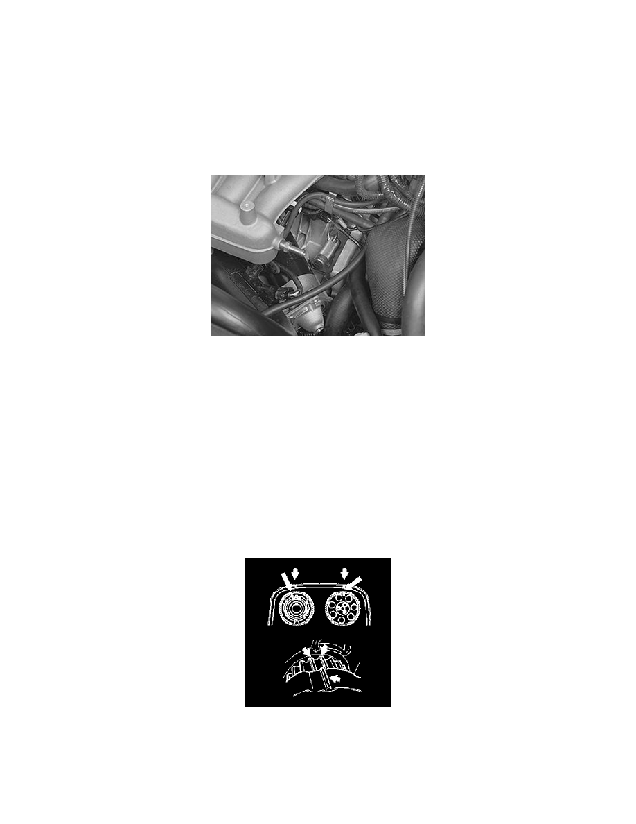
Turn the crankshaft back counter-clockwise until it stops against the drift.
Check that the marking on the crankshaft timing gear pulley corresponds with the marking on the oil pump.
Installation
Note!
The purpose of the section, "Installing the VVT unit/timing gear pulley", described here is to ensure that the VVT unit is correctly
positioned and to reset the camshaft timing gear pulley to the correct position using the markings made at the factory. This is to ensure that
the conditions are correct for any later fault-tracing.
Installing the timing gear pulley for the camshafts. The toothed belt with the Variable valve timing (VVT) unit
Slacken off, but do not remove, the screws which secure the timing gear pulley to the variable Valve Timing (VVT) unit.
Press the timing gear pulley/variable Valve Timing (VVT) unit on to the camshaft.
Install the center screw which secures the variable Valve Timing (VVT) unit to the camshaft. Tighten slightly.
Rotate the variable valve timing (VVT) unit counterclockwise to its stop.
Remove the center screw.
Position the upper timing cover.
Turn the timing gear pulley clockwise until the screws at the oval holes are in the limit position.
Continue turning clockwise until the timing gear pulley marking is 1 cog before the marking on the upper timing cover.