
V50 L5-2.4L VIN 39 B5244S7 (2005)
The function of the leak diagnostic unit is to pressurize the fuel tank system during leak diagnostics.
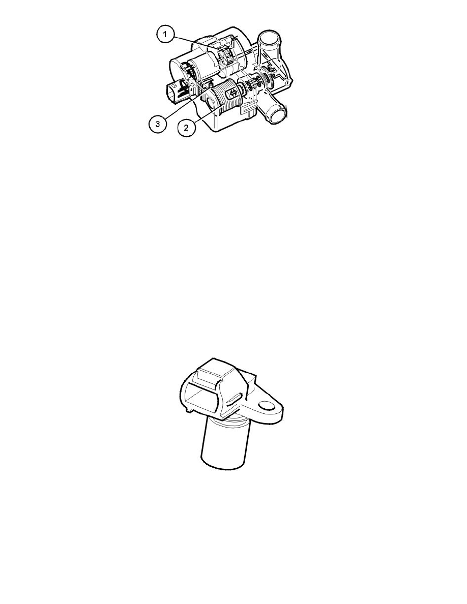
The leak diagnostic unit consists of a plastic housing with:
1. electrical air pump
2. a valve / solenoid which governs the air flow in the unit
3. a heater element (PTC resistor) which warms up the pump.
The electrical pump, valve and heater element in the unit are supplied with voltage by the system relay. The pump, valve and heater element are
grounded (control) in the engine control module (ECM).
When leak diagnostics are not active, the valve is held open to ambient air for EVAP control to be carried out.
During leak diagnostics the pump in the leak diagnostic unit starts. The valve in the unit is operated by the engine control module (ECM) by grounding
the different circuits internally in the engine control module (ECM).
The Engine control module (ECM) checks the fuel tanks system for leaks by pressurizing the system and at the same time monitoring a number of
relevant parameters. Also see: Leak diagnostics (certain markets only) See: Powertrain Management/Computers and Control Systems/Description and
Operation/Leak Diagnostics (Certain Markets Only)
The engine control module (ECM) can diagnose the leak diagnostic unit.
The valve in the leak diagnostic unit can be activated.
The leak diagnostic unit is at the upper front edge of the fuel tank.
Part 2
Design (Continued)
Engine speed (RPM) sensor
The engine speed (RPM) sensor provides the Engine Control Module (ECM) with information about the speed and position of the crankshaft. The
Engine Control Module (ECM) is able to use the signal from the engine speed (RPM) sensor to determine when a piston is approaching top dead center
(TDC). However it is unable to use the signal from the engine speed (RPM) sensor to determine whether the piston is in the combustion stroke or
whether the exhaust valve is open (exhaust stroke). The signal from the camshaft position (CMP) sensor is also required to determine the operating cycle
of the engine. See also: Camshaft position (CMP) sensor
The signal from the engine speed (RPM) sensor is also used to check the engine for misfires. For more information, see: Misfire diagnostic See:
Powertrain Management/Computers and Control Systems/Description and Operation/Misfire Diagnostics
There is a steel ring with stamped holes welded to the rim of the primary section (the section fixed to the crankshaft) of the flywheel.
The holes are positioned with a gap of 6° between each hole. This arrangement creates a hole for each tooth. There are 360° in one revolution. 6°
between each hole means that there are 60 holes. However two holes are not stamped, to create a reference position (long gap - missing tooth) for the
crankshaft. The first tooth after the reference position is located 84° before TDC on cylinder 1. See: Function See: Powertrain Management/Computers