XC90 2.5T AWD L5-2.5L Turbo VIN 59 B5254T2 (2003)

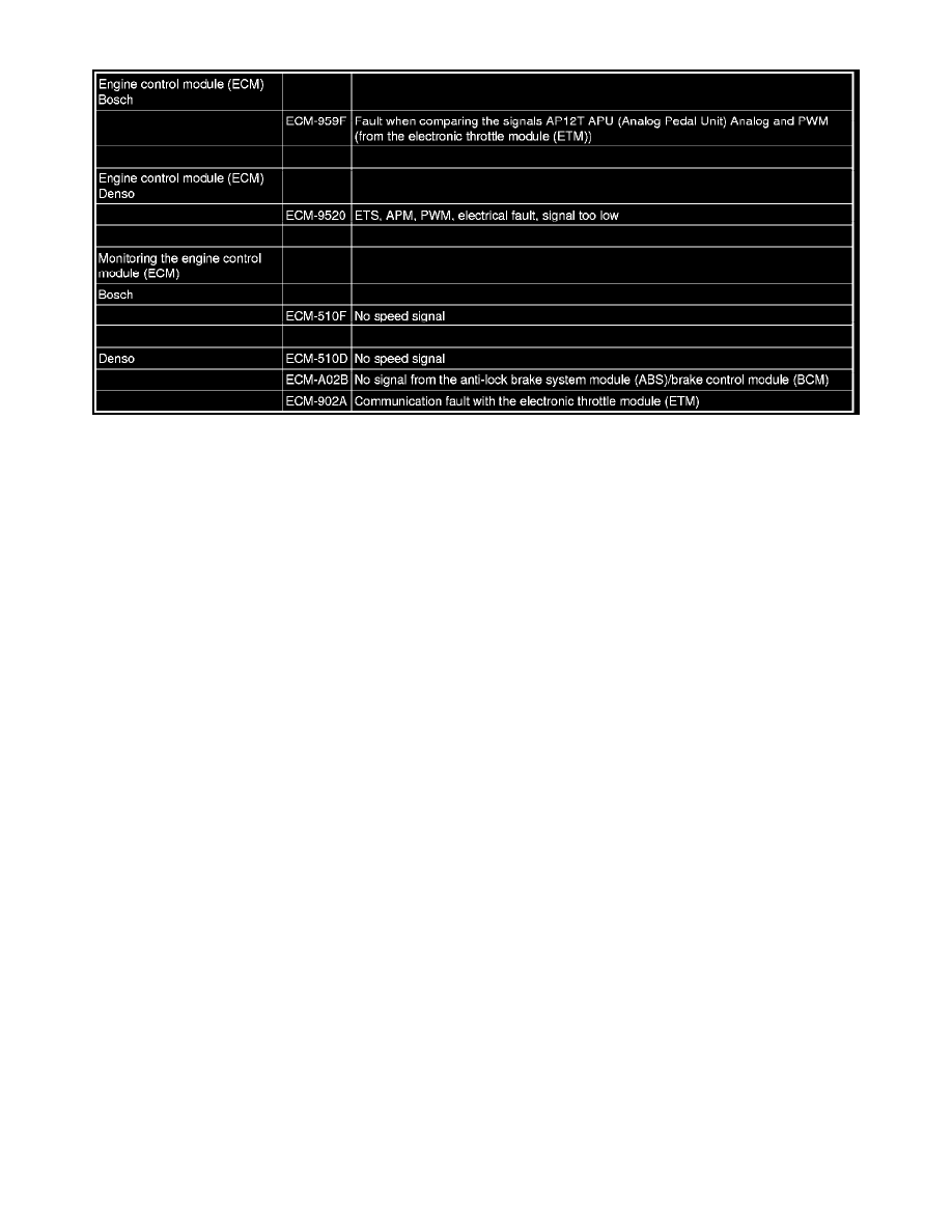
table below.
Part 2
Information about the CAN network, structure and function (Continued)
Multiple diagnostic trouble codes (DTCs) and extended diagnostics (counters and freeze frames)
The detection time for faults in the CAN network varies depending on the diagnostic trouble code (DTC). This means that for different fault occurrences,
different diagnostic trouble codes (DTCs) can be stored in different control modules. Several diagnostic trouble codes (DTCs) in different control
modules can be confusing and must be investigated at the start of fault-tracing to check for any link between the various codes.
It is now possible to read off extended diagnostic trouble code (DTC) information in VIDA, normally counters and frozen values. This can also help with
fault-tracing on the CAN network as it can provide information about diagnostic trouble codes (DTCs) that are stored simultaneously. Remember that the
function using counters can be implemented differently in different control modules, which can make it difficult to compare cycles between different
control modules.
When performing fault-tracing on a car with many intermittent E003 and CEM-1A51 to CEM-1A66 diagnostic trouble codes (DTCs), this can be made
easier by checking the affected control modules. Copy the diagram in the service manual, Data communication for the relevant car model, and write
down all diagnostic trouble codes (DTCs) and counters at the relevant control modules. Check any conclusions can be drawn from where the diagnostic
trouble codes (DTCs) are stored. If the diagnostic trouble codes (DTCs) are in control modules at one end of the CAN network, this can give an
indication of where the fault may be located.
Limp-home modes and characteristics of control modules in the event of faults in the CAN network
When a control module cannot receive messages from the central electronic module (CEM) it will go into Limp-home mode. In such cases, the control
module can retain part of its functionality. The remaining functionality varies in different control modules. If a fault occurs after a control module has
been started up, it will normally retain the most recent values as the Limp-home values. There are exceptions, such as the fuel gauge in the driver
information module (DIM).
Some clear examples for the low speed side network:
-
Driver information module (DIM):
As the driver information module (DIM) only displays signals received from the CAN network, it will soon be evident if signals are lost. The display of
various signals will disappear at slightly different times due to some filtering of the signals in the driver information module (DIM). The values on the
gauges are normally frozen for around ten seconds before dropping to zero and the driver information module (DIM) shuts down. If only one control
module has disappeared from the network, the driver information module (DIM) can display the first indication of this. An example of this is where the
rear electronic module (REM) stops communicating, which is indicated by the fuel gauge dropping to zero
-
Climate control module (CCM):
This control module must retain some of its functionality even if the CAN communication is lost. It is also a very good indication of whether the CAN
communication has been lost, as the LEDs will light up exactly ten seconds after the ignition key has been turned to positions one or two. Other
symptoms: if the AC compressor is not working, apart from the first second when the function is checked by the engine control module (ECM), this can
indicate a fault in the climate control module (CCM)>central electronic module (CEM)>engine control module (ECM) chain. Another very obvious
symptom is that the blower fan continues to operate for up to ten minutes after the key is removed from the ignition switch. This is because the climate
control module (CCM) is powered via Extended-X from the central electronic module (CEM). The climate control module (CCM) normally switches off
the blower fan and other functions when it does not receive a signal over the CAN network after the ignition key has been removed. If there is no CAN
communication, the climate control module (CCM) will continue to operate until the central electronic module (CEM) switches off the power supply
-
Driver door module (DDM)/Passenger door module (PDM):
