
RDX L4-2.3L Turbo (2008)
Network "Loss of Communication" Error Checking Function
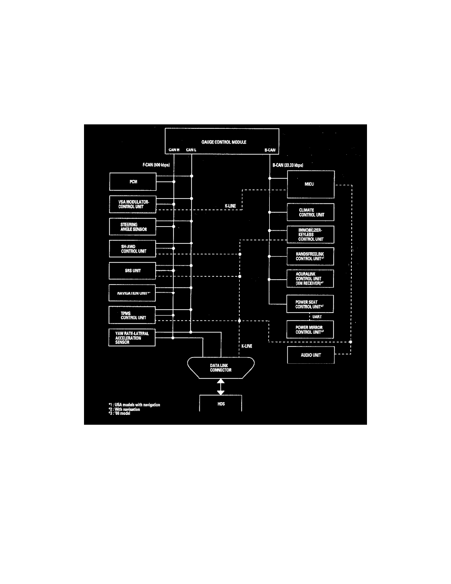
The ECUs on the CAN circuit send messages to each other. If there are any malfunctions on the network, the LCD display on the gauge control module
can indicate the error messages by entering the gauge self-diagnostic function.
Self-diagnostic Function
By connecting the HDS to the data link connector (DLC), the HDS can retrieve the diagnostic results from the MICU via a diagnostic line called
K-LINE. The K-LINE is distinguished from the CAN line, and connected to the CAN related ECUs. The MICU is a gateway between the HDS and
B-CAN related ECUs, and sends B-CAN diagnostic results to the HDS. When performing a function test with the HDS, the HDS sends an output signal
through the K-LINE to the MICU. The MICU either relays the request to another ECU, or commands the function its self.
Wake-up and Sleep Function
The multiplex integrated control system has "wake-up" and "sleep" functions to decrease parasitic draw on the battery when the ignition switch is OFF.
-
In the sleep mode, the MICU stops functioning (communication and CPU control) when it is not necessary for the system to operate.
-
As soon as any operation is requested (for example, a door is unlocked), the related control unit in the sleep mode immediately wakes up and
begins to function.
-
When the ignition switch is turned OFF, and the driver's door is opened, then closed, there is a delay about 40 seconds before the control unit goes
from the wake-up mode to the sleep mode.
-
The sleep mode will not function if any door is opened or if a key is in the ignition.
-
The draw is reduced from 200 mA to less than 35 mA when in the sleep mode.
NOTE: Sleep and Wake-up Mode Test.
Fail-safe Function
To prevent improper operation, the MICU has a fail-safe function. In the fail-safe mode, the output signal is fixed when any part of the system