
RL V6-3.5L (2007)
Data Link Connector: Testing and Inspection
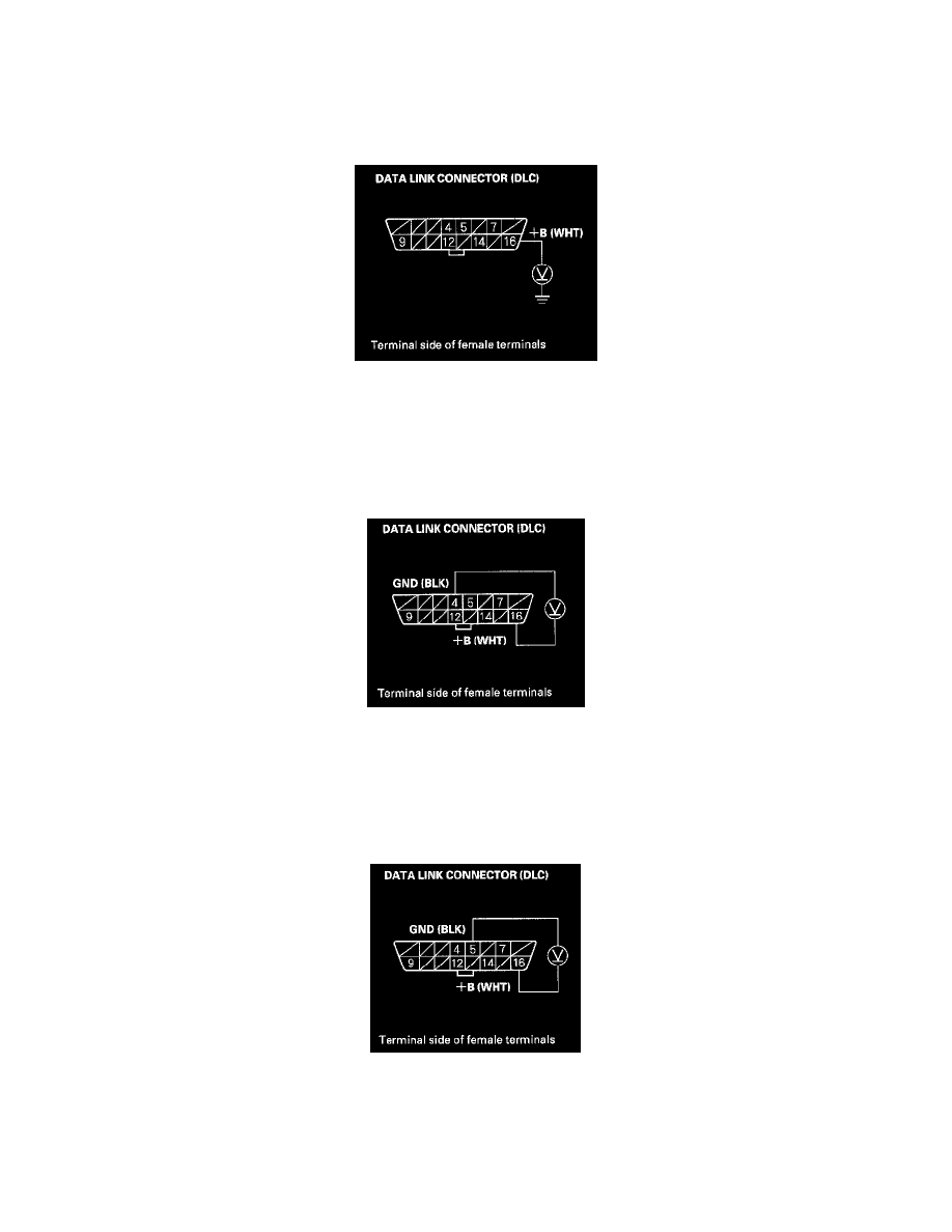
DLC Circuit Troubleshooting
NOTE:
-
If the PCM does not communicate with the HDS, do this troubleshooting procedure.
-
Check that MIL circuit is normal, then do this troubleshooting.
1. Measure voltage between DLC terminal No. 16 and body ground.
Is there battery voltage?
YES - Go to step 2.
NO - Repair open in the wire between DLC terminal No. 16 and the No. 8 FI ECU (PCM) (15 A) fuse in the under-hood fuse/relay box.
2. Measure voltage between DLC terminals No. 4 and No. 16.
Is there battery voltage?
YES - Go to step 3.
NO - Repair open in the wire between DLC terminal No. 4 and body ground (G501).
3. Measure voltage between DLC terminals No. 5 and No. 16.
Is there battery voltage?
YES - Go to step 4.
NO - Repair open in the wire between DLC terminal No. 5 and body ground (G501).