
RL V6-3.7L (2009)
Information Bus: Component Tests and General Diagnostics
Troubleshooting - B-CAN System Diagnosis Test Mode 1 and Test Mode 2 (Without the HDS)
Troubleshooting - B-CAN System Diagnosis Test Mode 1 and Test Mode 2 (without the HDS)
Special Tools Required
-
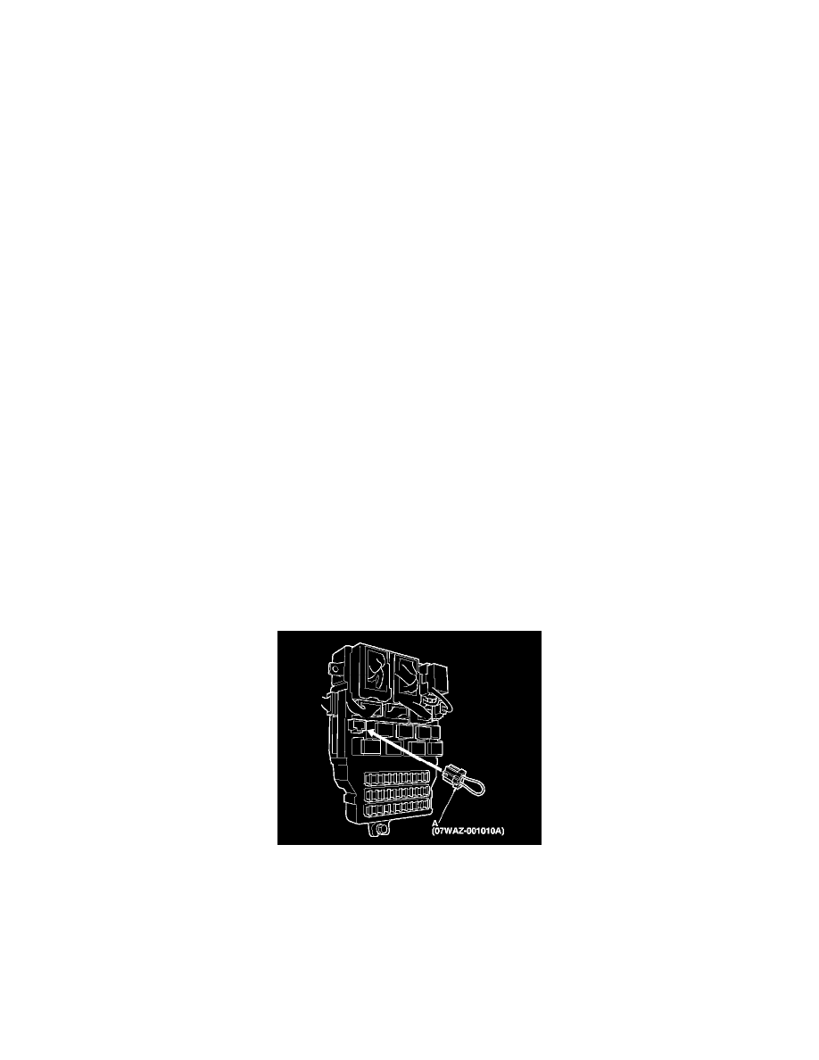
MPCS service connector 07WAZ-001010A
Test Mode 1
Do this diagnosis if the HDS is not available.
1. Check the No. 7 (10 A) and No. 21 (10 A) fuses in the driver's under-dash fuse/relay box.
Are the fuses OK?
YES - Go to step 2.
NO - Find and repair the cause of the blown fuse.
2. Remove the left kick panel, See: Body and Frame/Interior Moulding / Trim/Scuff Plate/Service and Repair/Interior Trim Removal/Installation -
Front Door Sill Area and the driver's dashboard under cover.
3. Turn the ignition switch to ON (II), and move the interior lights switch to the "DOOR" position.
4. Connect the MPCS service connector (A) to the MCIC socket (B) in the driver's under-dash fuse/relay box.
5. Wait 5 seconds, and watch the map lights. When the system enters Mode 1, the front and rear map lights will flash quickly once, and a double
beep will be heard.
6. If there is a DTC, the map lights and ignition key light will blink, pause, then repeat the DTC as long as the ignition switch is turned to ON (II).
Is there a repeating DTC?
YES - Count the blinks, then go to step 7.
NO - Go to step 8.
7. About 1 second after you go into self-diagnostic Mode 1, the map lights will indicate the DTC, and repeat it every 3 seconds. If there is more than
one DTC, the system will indicate them in ascending order, beginning with the DTC with the lowest numerical value. Troubleshoot the DTCs as
indicated below:
-
DTC 2, 3, 4 and 5 simultaneously: Check for an open in the LT GRN wire between MICU D11 and relay control module J7, LT GRN wire
between MICU N28 and combination switch control unit No. 4, LT GRN wire between MICU J4 and driver's MPCS unit A28, and LT GRN
wire between MICU N22 and gauge control module B17. If the wire is OK, substitute a known-good driver's under-dash fuse/relay box,
under-hood fuse/relay box, gauge control module, wiper/washer switch, and driver's MPCS unit one at a time, in that order, and recheck for the
DTCs after each substitution.
-
DTC 1 only: Go to MICU input test. See: Multiplex Integrated Control System MICU Input Test