
RL V6-3.7L (2009)
-
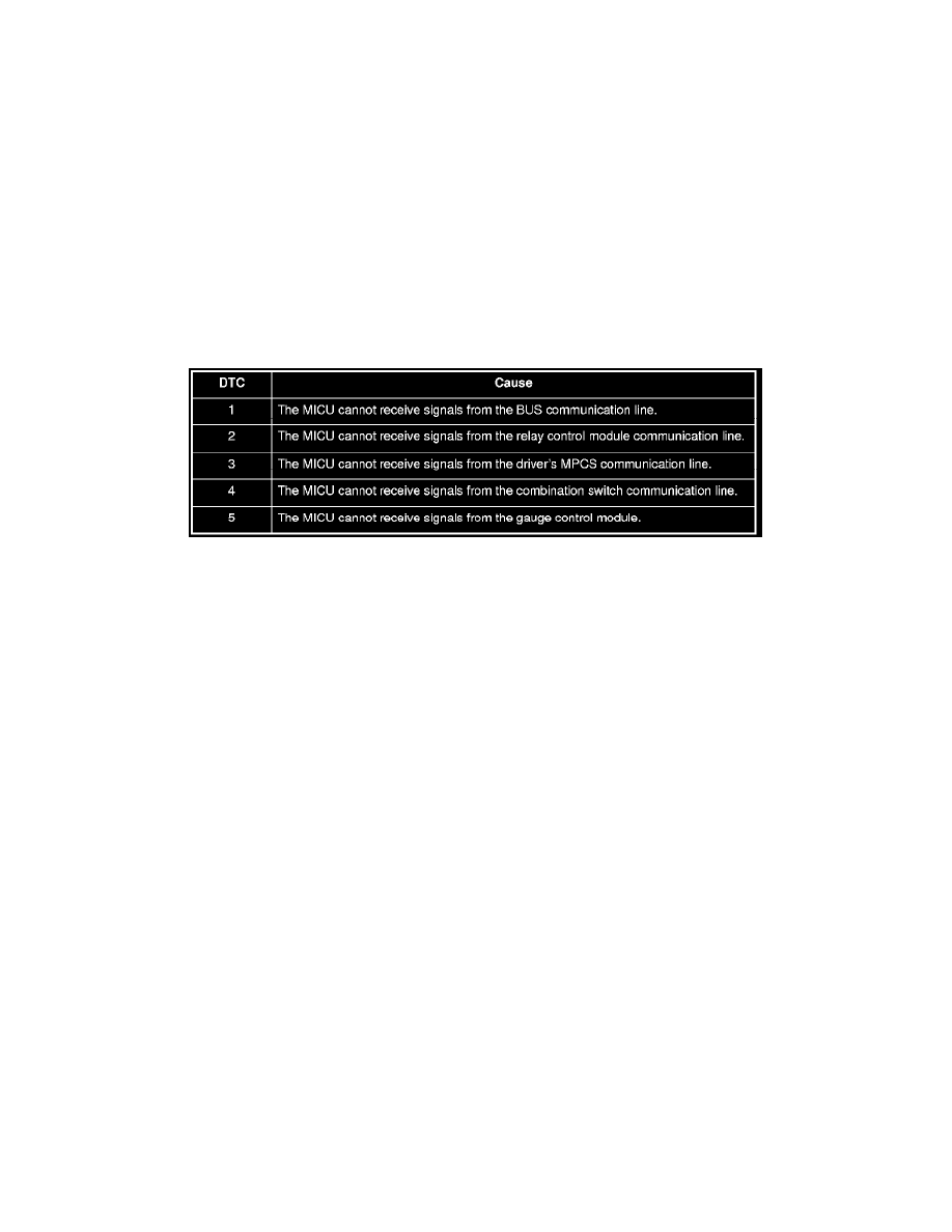
DTC 2 only (no other DTCs present): Go to the relay control module input test. See: Power and Ground Distribution/Testing and
Inspection/Relay Control Module Input Test If all inputs are OK, substitute a known-good relay control module and then a MICU, one at a
time, and then check for DTCs. If a DTC recurs after a substitution, replace that unit.
-
DTC 3 only (no other DTCs present): Go to the driver's MPCS unit input test. See: Multiplex Integrated Control System Driver's MPCS Unit
Input Test If all inputs are OK, substitute a known-good driver's MPCS unit and then a MICU, one at a time, and then check for DTCs. If a
DTC recurs after a substitution, replace that unit.
-
DTC 4 only (no other DTCs present): Go to the combination switch control unit input test. See: Lighting and Horns/Testing and
Inspection/Component Tests and General Diagnostics/Combination Switch Control Unit Input Test If all inputs are OK, substitute a
known-good wiper/washer switch and then a MICU, one at a time, and then check for DTCs. If a DTC recurs after a substitution, replace that
unit.
-
DTC 5 only (no other DTCs present): Go to the gauge control module input test. See: Instrument Panel, Gauges and Warning
Indicators/Testing and Inspection/Component Tests and General Diagnostics/Gauge Control Module Input Test If all inputs are OK, substitute
a known-good gauge control module and then a MICU, one at a time, and then check for DTCs. If a DTC recurs after a substitution, replace
that unit.
8. Check for B-CAN DTCs indicated by the gauge control module. See: Instrument Panel, Gauges and Warning Indicators/Testing and
Inspection/Initial Inspection and Diagnostic Overview/Gauge Control Module DTC Display
Are any DTCs indicated?
YES - Go to step 9.
NO - Go to step 11.
9. Record all DTCs and sort them by type using the DTC Troubleshooting.
10. Troubleshoot the DTCs in these order:
-
Battery voltage DTCs
-
Internal error DTCs
-
Loss of communication DTCs (begin with the lowest number first; for example, if DTC B1005 and B1008 are retrieved, troubleshoot B1005
first)
-
Signal error DTCs
Test Mode 2
11. Remove the MPCS service connector from the driver's under-dash fuse/relay box socket for 5-10 seconds, then re-insert it to enter Mode 2. When
the system enters Mode 2, the front and rear map lights will flash two times quickly.
NOTE: If the MPCS connector is disconnected for too short or too long of a time, or the ignition switch is turned to LOCK (0), the system will
return to Test Mode 1.
12. The following tables list the circuits that can be checked in Test Mode 2. Operate the switch that is most closely related to the problem. If the
circuit is OK, the map lights will blink once. If the circuit is faulty, there will be no indication.
MICU