
TL V6-3.5L (2007)
39. Measure voltage between body ground and ECM/PCM connector terminals A1, A2, A3, and B15 individually.
Is there more than 0.2 V?
YES - Repair open in the wire(s) that had more than 0.2 V between G101 and the ECM/PCM (B15, A1, A2, A3).
NO - Go to step 40.
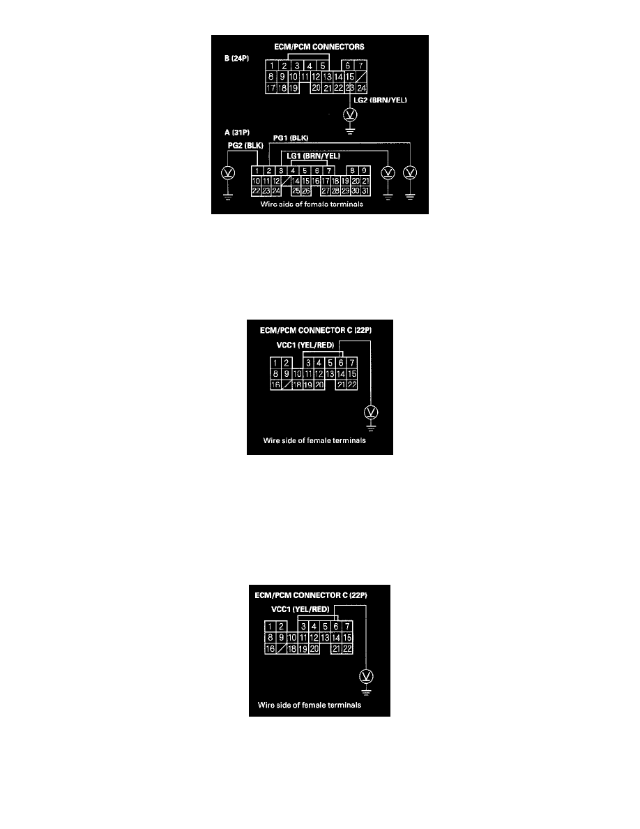
40. Measure voltage between ECM/PCM connector terminal C6 and body ground.
Is there about 5 V?
YES - Go to step 48.
NO - Go to step 41.
41. Turn the ignition switch OFF.
42. Disconnect the connector from each of these sensors, one at a time, and measure voltage between ECM/PCM connector terminal C6 and body
ground with the ignition switch ON (II).
-
MAP sensor
-
Output shaft (countershaft) speed sensor
Is there about 5 V?