
TL FWD V6-3.5L (2009)
Fuel Gauge Sender: Testing and Inspection
Fuel Gauge Sending Unit Test
Without SH-AWD
NOTE: For the fuel gauge system circuit diagram, refer to the Gauges Circuit Diagram.
1. Check the No. 12 METER (7.5 A) fuse in the driver's under-dash fuse/relay box before testing.
2. Check for body electrical system DTCs.
-
If no problem is found, go to step 3.
-
If DTC B1175 or B1176 is indicated, go to the indicated DTC's troubleshooting.
3. Turn the ignition switch to LOCK (0), or press the engine start/stop button to select the OFF mode.
4. Remove the rear seat cushion. See: Body and Frame/Seats/Service and Repair/Rear Seat Removal/Installation
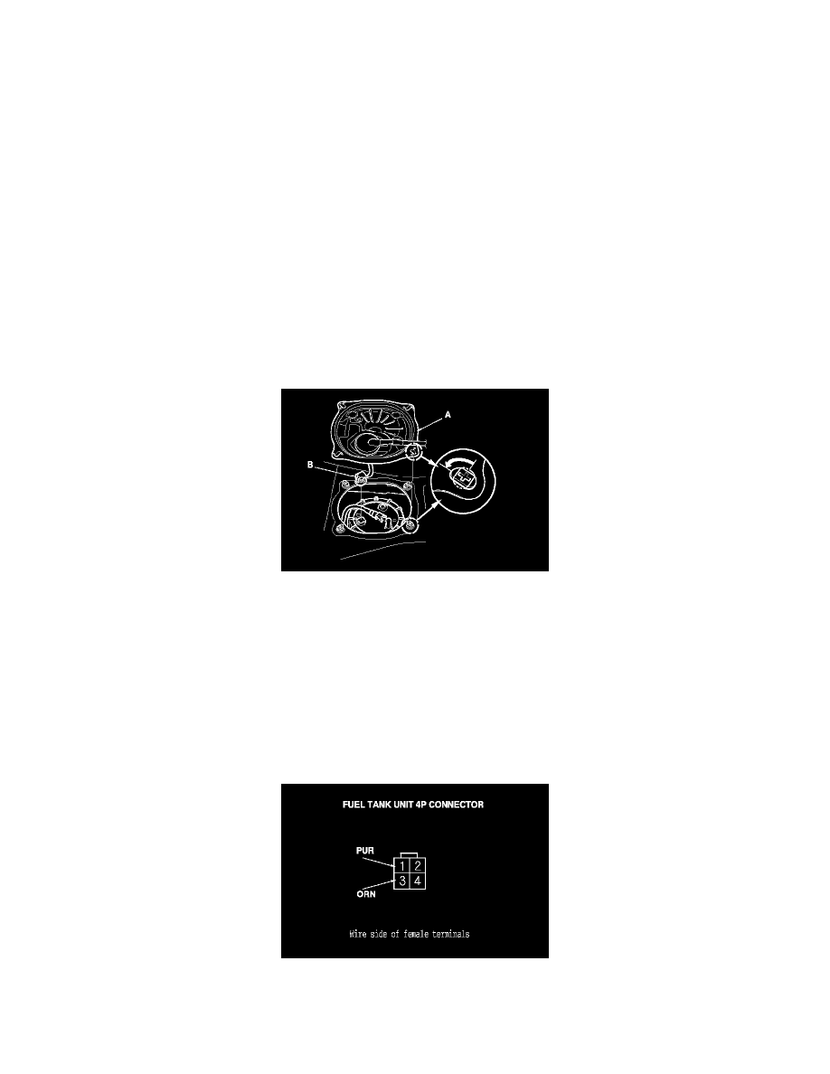
5. Remove the access panel (A) from the floor.
6. Disconnect the fuel tank unit 4P connector (B).
7. Measure the voltage between fuel tank unit 4P connector terminals No. 1 and No. 3 with the ignition switch turned to ON (II), or press the engine
start/stop button to select the ON mode. There should be battery voltage.
-
If the voltage is OK, go to step 8.
-
If the voltage is not as specified, check for:
-
a short in the PUR wire to ground.
-
an open in the PUR or the ORN wire.
8. Turn the ignition switch to LOCK (0), or press the engine start/stop button to select the OFF mode.
9. Remove the fuel tank unit from the fuel tank. See: Service and Repair/Fuel Tank Unit Removal and Installation
10. Measure the resistance between fuel tank unit 4P connector terminals No. 1 and No. 3 with the float at E (EMPTY), LOW (LOW FUEL
INDICATOR), 1/2 (HALF FULL), and F (FULL) positions.
If you do not get the following readings, replace the fuel gauge sending unit. See: Fuel Pump/Service and Repair/Fuel Pump/Fuel Gauge Sending
Unit Replacement