
General description
- Make
- Alfa Romeo
- Model
- 145/146 Electrical System Diagnosis Manual, Volume 3
- Year
- 1994–2001
- Section
- Heated Screen and Mirrors › General description
GENERAL DESCRIPTION
The rearscreen and wing mirrors (in some countries/versions only) incorporate a wire that heats the surfaces it contacts when it is crossed by current, thereby quickly demisting and/or defrosting them.
The device is actuated by pressing the corresponding switch on the lever unit which controls the heated rearscreen relay.
A warning light on the instrument cluster indicates when the device is operating.
Actuation of the heated rearscreen also turns on the wing mirror defrosting function (if installed).
From chassis no.... the supply for door mirror defrosting is through a dedicated line, with specific relay and fuse.
FUNCTIONAL DESCRIPTION
The line of fuse F12 of fusebox G1 supplies the rearscreen heating relay switch I2, the coil of which is supplied from the ignition switch and energized by an earth signal leading from switch /// on the lever unit B68.
From Model Year '97, the relay includes an electronic device which turns off the device after 5 minutes from 1st engagement and shorter times after any subsequent engagements.
Relay switch I2 is also located in fusebox G1.
When the contact of relay switch I2 closes the battery voltage supplies the line, which protected by fuse F12 of G1, reaches the rearscreen O1 and the resistances of the wing mirrors O19 (left) and O18 (right).
From chassis no.... the mirrors are supplied by the line of fuse G394 (7.5A) through relay I45.
Thr same supply signal is also sent to the instrument cluster C10 to turn on the corresponding warning light.
WARNING: from Model Year '97 the warning light is in a different position - See "INSTRUMENT CLUSTER".
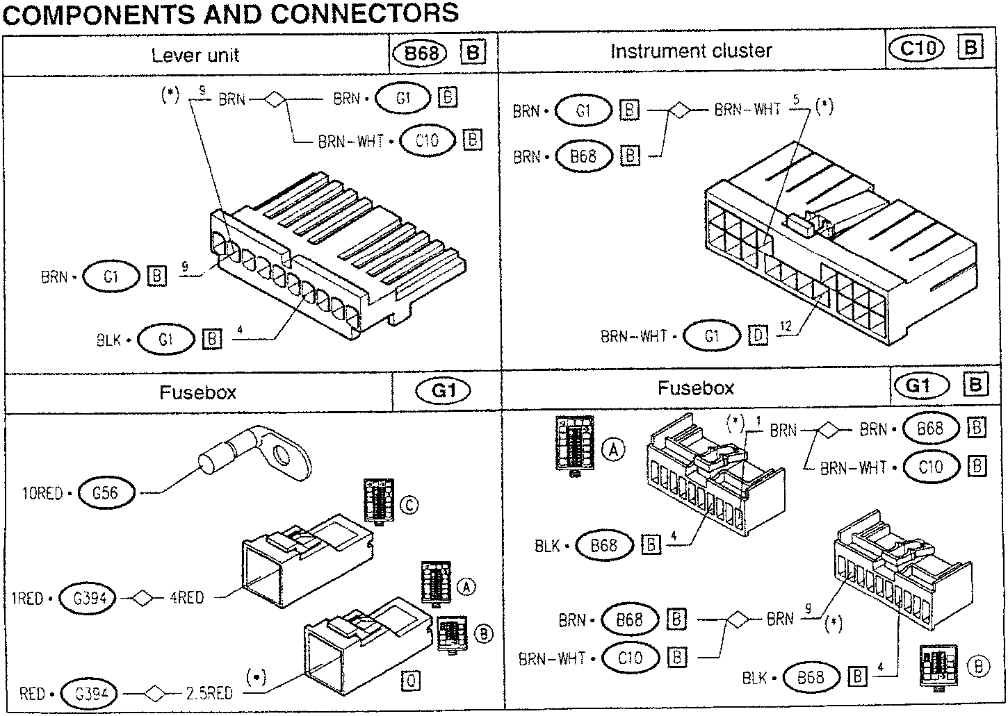
COMPONENTS AND CONNECTORS
| Lever unit | B68 | B | |
|---|---|---|---|
| (*) | 9 BRN-♦-BRN • G1 B | BRN-WHT • C10 B | |
| BRN • G1 B | 9 | BLK • G1 B | 4 |
| Instrument cluster | C10 | B | |
|---|---|---|---|
| BRN • G1 B | ♦-BRN-WHT 5 (*) | ||
| BRN • B68 B | BRN-WHT • G1 D 12 | ||
| Fusebox | G1 | B | |
|---|---|---|---|
| 10RED • G56 | ♦-4RED | 1RED • G394 | ♦-2.5RED |
| RED • G394 | ♦-2.5RED | ||
| Fusebox | G1 | B | |
|---|---|---|---|
| BRN • B68 B | ♦-BRN 9 (*) | BLK • B68 B | 4 |
| BRN-WHT • C10 B | ♦-BRN 9 (*) | BLK • B68 B | 4 |
(*) from chassis no.
PA49300000008
(*) Model Year '97
- 3 -
6-1997
Parts & tools for this job For 1994 Alfa Romeo 145/146
- TOOLTrim removal tool kitSearch: trim removal tool kit
- PARTTouch-up paintSearch: Alfa Romeo touch up paint
- PARTPanel clip assortmentSearch: Alfa Romeo panel clips assortment
Links open Amazon search results in a new tab. As an Amazon Associate I earn from qualifying purchases.