
Operation of the circuit
- Make
- Alfa Romeo
- Model
- 145/146 Factory Service Manual
- Year
- 1994–1999
- Section
- Engine cooling system (Twin Spark 16V) › Operation of the circuit
OPERATION OF THE CIRCUIT
After cooling the engine, the fluid passes through the cylinder head to the thermostatising unit. From here, if its temperature is below 83 °C, it is withdrawn by the pump (1) via a longitudinal coolant fluid return manifold (11) on the lefthand side of the cylinder head. Conversely if the temperature exceeds this value, it is ducted by the opening of the thermostat towards the radiator (4). After cooling in the radiator, the fluid returns, again through the longitudinal manifold, to the pump which channels it into the engine. From the thermostatic cup the coolant fluid is also sent: - to warm the throttle body (8) from which it flows to the header tank (7) also relieving air from the system; - to the heater (6) of the climate control system and then return to the longitudinal manifold; - to the heat exchanger (12) for cooling the engine oil from which it is ducted directly into the longitudinal manifold for coolant fluid return to the pump. The header tank supplies the engine cooling system via a special connection hose to the longitudinal manifold.
WATER PUMP
The water pump is of the centrifugal type with blades. It is fastened to the cylinder head and operated through the timing gear belt, by the crankshaft. An O-Ring ensures tightness between the cylinder head and pump. The water pump operates constantly thereby ensuring the continuous circulation of the coolant fluid.
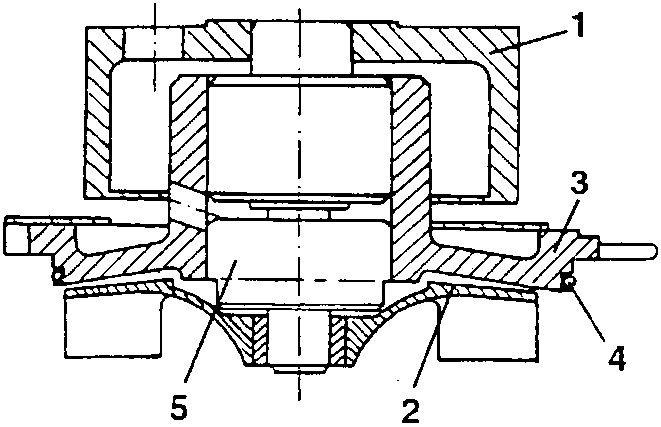
- Pulley
- Impeller
- Pump casing
- O-Ring
- Bearing
REMOVING/REFITTING (For engines without counter-rotating shafts)
- Set the car on a lift.
- Disconnect the battery (-) terminal.
- Drain the engine coolant fluid (see specific paragraph).
- Slacken the screws and move aside the header tank without disconnecting the hoses.
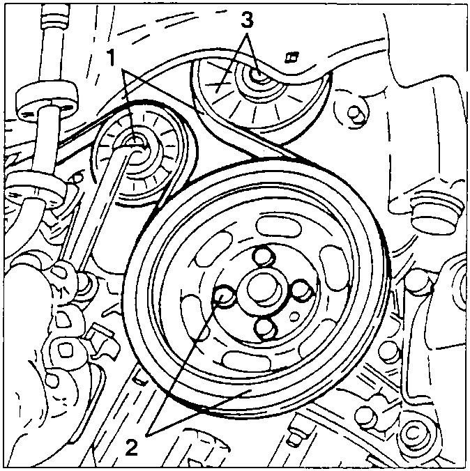
- Raise the car and working as illustrated on the belt tensioner, loosen the tension of the auxiliary components drive belt and remove it.
- Slacken the four fastening screws and remove the auxiliary components drive pulley.
- Slacken the fastening screw and remove the auxiliary components drive belt guide.
- Slacken the lower screws fastening the timing gear drive belt guard.
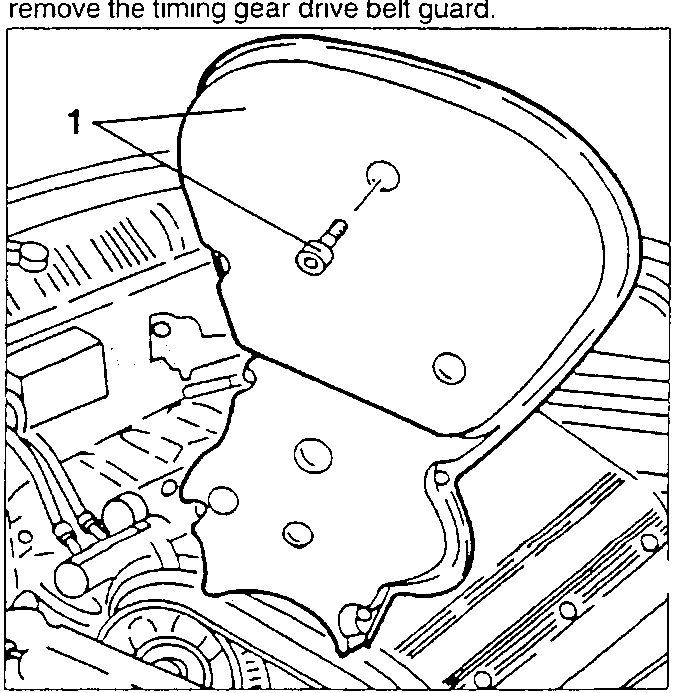
- Lower the car, slacken the remaining screws and remove the timing gear drive belt guard.
Parts & tools for this job For 1994 Alfa Romeo 145/146
- TOOLDigital multimeterSearch: automotive digital multimeter
- PARTAssorted fuse kitSearch: car fuse assortment kit
- TOOLWire crimper and connector kitSearch: wire crimper connector kit
Links open Amazon search results in a new tab. As an Amazon Associate I earn from qualifying purchases.