
Foreword
- Make
- Alfa Romeo
- Model
- 155 Factory Service Manual
- Year
- 1992–1998
- Section
- General description › Foreword
FOREWORD
Different instrument clusters are installed on the 155 depending on the versions: in addition to the “base” cluster A, the only one installed on the first cars (up to chassis no. ...), cluster B is supplied with more sporting features and instruments with "depth effect".
On other versions (1.7 and 1.8 T.S.) the simplified cluster C is installed, in which the warning lights and indicators are reduced to the essential.
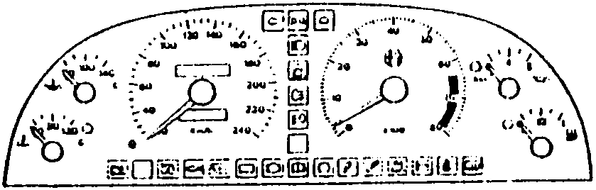
“Basic” INSTRUMENT PANEL: A
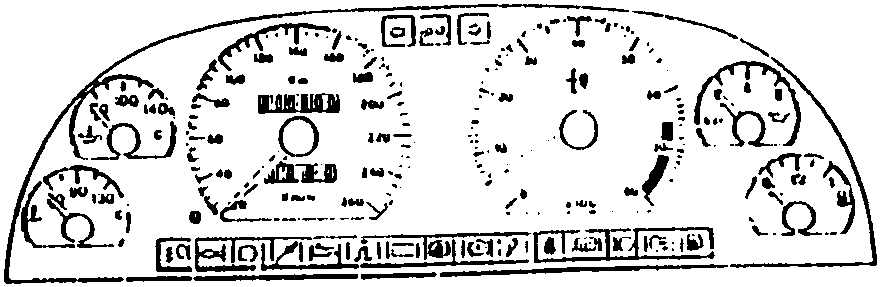
Spons type INSTRUMENT PANEL: B
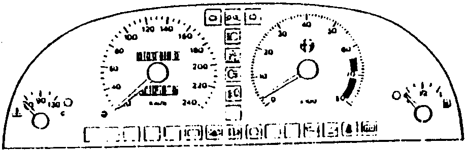
Simplified INSTRUMENT PANEL: C
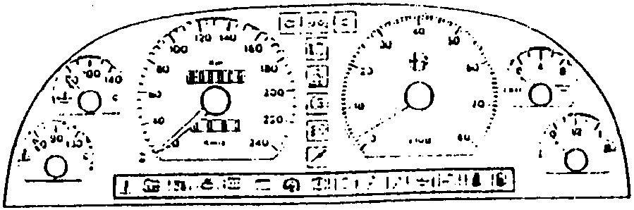
‘95 Version INSTRUMENT PANEL: D
GENERAL DESCRIPTION
The instrument panel supplies information and indications relative to the state of the vehicle which are indispensable for safe and relaxed driving.
The instrument is of the analog type with two large indicators for the speedometer and the rev counter, and other indicators for engine oil pressure and temperature. Fuel level and engine coolant temperature.
Numerous, evident warning lamps complete the information available to the driver.
N.B. The instrument panel is manufactured as a single component: all the internal connections are carried on a printed circuit which unites the instrument contacts and the various warning lamps. It is not therefore possible to carry out repairs apart from the simple operation of replacing the warning light bulbs.
Note: The wiring diagram has been divided into 6 parts
- The first five charts describe some of the specific functions which are not given elsewhere and which are connected only to the indications on the instrument panel. Other functions, particularly the warning lamps, are given in the system or installation diagrams, or to which they refer—for example, the dipped beam headlight warning lamp is given in the diagram “Main and dipped beam headlights”, etc.
- The sixth chart gives all the internal connections on the printed circuit
N.B.: The first chart illustrates the connections which supply power (+) and ground (-). In the successive charts, these lines are not given even though at least one of them is implied, e.g., and grounded signal reaching a warning lamp implies that the warning lamps connect to the power supply inside the instrument; and this connection is indicated with the symbol (+) or (-), and can easily be consulted in the internal chart.
The instrument panel lighting is supplied when the sidelights are switched on and is regulated by a rheostat (10 Ω described in a separate section “Interior lights”).
Parts & tools for this job For 1992 Alfa Romeo 155
- TOOLDigital multimeterSearch: automotive digital multimeter
- PARTAssorted fuse kitSearch: car fuse assortment kit
- TOOLWire crimper and connector kitSearch: wire crimper connector kit
Links open Amazon search results in a new tab. As an Amazon Associate I earn from qualifying purchases.