
Stop light check
- Make
- Alfa Romeo
- Model
- 155 Factory Service Manual
- Year
- 1992–1998
- Section
- Functional Description › Stop light check
Check Panel control unit
The Check Panel N59 processes the vanous signals and sends them to the display C16 through the lines that exit pins 1, 3, 4 and 6 of connector N of the fusebox G1 where the control unit N59 is located.
The control unit is turn-key supplied via fuse F15 (10A) to pin 5 of connector O of G1, while a ground reaches the control unit from pin 1 of the connector.
The control unit checks the electrical charge in the controlled circuits by way of a shunt ("SH1", "SH2"...), inserted in the circuits of fusebox G1 on the lines carrying the signals to be checked by the control unit N59.
In the following three charts the control unit N59 connections are illustrated along with the various controlled functions:
Stop light check
The control unit N59 is connected to the two contacts of the stop light switch H3 via pins 9 and 12 of connector H in G1.
The control unit carries out two distinct checks through this signal:
- - the first (only carried out when the brake pedal is depressed) checks for a possible anomaly in a single bulb or relative circuit, and the correct operation of the "working" contacts (H3) of switch H3 (see "Stop Lights").
- - the second (continuous operation) controls the supply to the circuit (fuse F2 of fusebox G1) and the correct operation of the contacts "at rest" (N.C.) of switch H3 (see "Stop Lights").
In both cases, if an anomaly is discovered, the control unit sends a signal to pin 4 of connector D of C16 to light up the relative warning lamp.
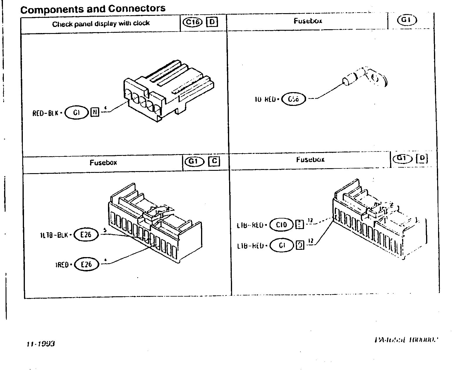
Components and Connectors
| Check panel display with clock | C16 D | Fusebox | G1 | |
|---|---|---|---|---|
| RED-BLK • G1 H 4 | [symbol] | 10 RED • C6 | [symbol] | |
| Fusebox | G1 C | Fusebox | G1 D |
|---|---|---|---|
| 1L18-BLK • E26 5 | [symbol] | L18-RED • C10 12 | [symbol] |
| IRE D • E26 4 | L18-RED • G1 12 |
Parts & tools for this job For 1992 Alfa Romeo 155
- TOOLDigital multimeterSearch: automotive digital multimeter
- PARTAssorted fuse kitSearch: car fuse assortment kit
- TOOLWire crimper and connector kitSearch: wire crimper connector kit
Links open Amazon search results in a new tab. As an Amazon Associate I earn from qualifying purchases.