
Components and Connectors
- Make
- Alfa Romeo
- Model
- 155 Factory Service Manual
- Year
- 1992–1998
- Section
- Functional Description › Components and Connectors
Electrical 26 – Heating, ventilation and air conditioningComponents and Connectors · page 1 of 2
The electromagnetic coupling which activates the compressor Q11 is controlled by relay Q22 located in the relay and fuse unit Q41.
Relays Q22 and Q23 located in unit Q41 have a key-activated coil (line protected by fuse F15 (10A) in G1). The power line on the other hand is supplied with battery voltage through fuse Q40 (15A) also located in unit Q41 and through fuse Q43 (50A) which protects the entire system.
The relay Q22 is activated by the Motronic ignition/injection system and consequently supplies 12 volts to the electromagnetic coupling in accordance with the following logic:
- The relay Q32 is activated by a signal coming from relay Q69 which is in turn activated by a signal coming from the compressor engagement switch Q68. This signal crosses the control knob Q4 and interrupts it when the knob is in the OFF position. In this state the compressor cannot be engaged. At the same time this signal commands the engagement of the electric fan at the first speed ("Electric Fan Control and Recirculation").
- Relay Q32 consequently sends a command signal to the pin 86 of the Motronic control unit S11.
- The control unit returns this signal from pin 48 of S11 to relay Q22 thus engaging the compressor but only after the internal logic has checked certain conditions (e.g. that the compressor is not engaged when maximum power is required from the engine). The control unit also checks that the signal at pin 85 of S11 coming from the minimum pressure switch (defroster) Q9 and from the minimum and maximum pressure switch (binary) Q20 is not interrupted, a situation which occurs when the pressure in the cooling system is either too high or too low in which case the command signal is not returned to activate the compressor.
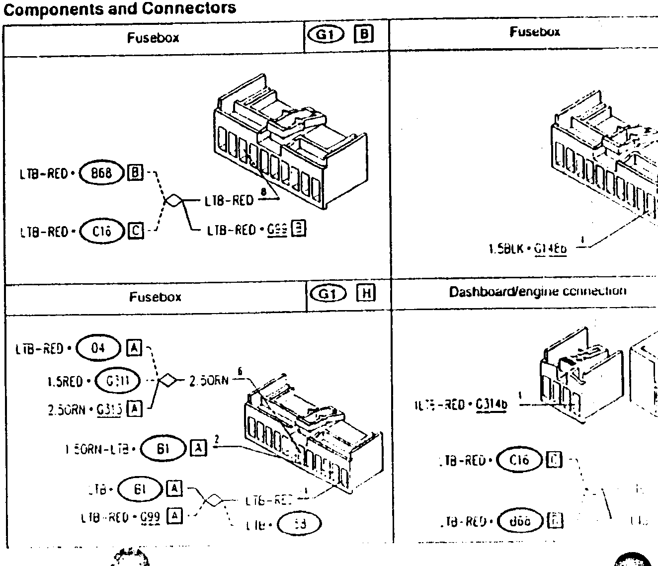
Components and Connectors
| Fusebox | G1 B | Fusebox | G1 G |
|---|---|---|---|
| LTB-RED • B68 B | LTB-RED • C16 C | 1.5BLK • G14Ed | |
| LTB-RED • GEE E | |||
| Fusebox | G1 H | Dashboard/engine connection | G99 B |
| LTB-RED • 04 A | 1.5RED • G311 | 2.5ORN • G313 A | ILTE-RED • G314b |
| 1.5ORN-LTB • B1 A | LTB-RED • C16 C | .TB-RED • d66 E | |
| LTB-RED • G99 A | LTB-RED • G313 A | LTB-RED • G314b |
Parts & tools for this job For 1992 Alfa Romeo 155
- TOOLA/C manifold gauge setSearch: AC manifold gauge set
- TOOLUV leak detection kitSearch: AC UV leak detection kit
- PARTCabin filterSearch: Alfa Romeo 155 1992 cabin filter
Links open Amazon search results in a new tab. As an Amazon Associate I earn from qualifying purchases.