
Description
- Make
- Alfa Romeo
- Model
- 155 Factory Service Manual
- Year
- 1992–1998
- Section
- Introduction › Description
DESCRIPTION
The first part (general description) describes the function of the circuit or system under examination and shows how it works: this is a condition which is necessary for each successive operation check and any troubleshooting found to be necessary.
The second part (functional description) shows the wiring diagram analytically, following the "flow" of the supply signals towards ground from the upper to the lower part.
The components are identified by the same alphanumerical codes used for the diagrams (and in the key at the end of this publication).
The components which need to be outlined and described from an electrical point of view (e.g. relays, contacts, fuses, connectors etc.) in order to be able to check the functioning in the successive fault diagnosis are also briefly described.
COMPONENTS AND CONNECTORS
A table lists all the components and connectors used in the wiring diagram of the section. For the intermediate connectors both parts are shown ("male" and "female").
Alongside the schematic diagram of the component can be found the representations of the cables indicated in the wiring diagram in question, indicating cross-section, colour and the component to which the cable is connected.
LOCATION OF COMPONENTS
A schematic diagram representing the silhouette of the vehicle makes it easy to find the various components of the circuit under examination, and to identify, where necessary, the route taken by the cables fixed to the body of the vehicle itself.
TROUBLESHOOTING
N.B. All the troubleshooting procedures given in this publication begin from the hypothetical situation that there is ONLY ONE FAULT in the system at any one time. In the unlikely event of simultaneous faults, it is necessary to unite more than one procedure.
If more than one circuit or system is out of use at the same time there are at least two situations which can be easily recognized: the malfunction affects a fuse protecting the various lines (for this refer to the section "Fusebox") or a defect affecting the ground point where the different lines converge (for this, refer to the section "Location of grounds").
TROUBLESHOOTING TABLE
A TROUBLESHOOTING TABLE follows the descriptions. The possible (and most frequent) faults which can affect the circuit are listed in this table: for each of these, the components which may be affected and the test to be carried out from among those given below are indicated.
In the example given below, the fault affecting function X involves components 1 and 5 and can be rapidly located by following test A
| Malfuction | Component | Test | |||
|---|---|---|---|---|---|
| 1 | 2 | 3 | 4 | 5 | |
| X | ● | ● | A | ||
| Y | ● | ● | ● | B |
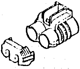
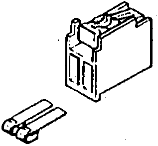
Some connectors are equipped with a secondary lock which prevents the terminals of the cables from becoming accidentally separated from the connector itself.
NOTE: ensure that the secondary lock is removed before removing the cable from the connector. When it is refitted, after connecting all the cables, replace the secondary lock.
The secondary lock may be one of a variety of different types depending on the connector to which it is fixed as shown in the following examples.

Parts & tools for this job For 1992 Alfa Romeo 155
- TOOLDigital multimeterSearch: automotive digital multimeter
- PARTAssorted fuse kitSearch: car fuse assortment kit
- TOOLWire crimper and connector kitSearch: wire crimper connector kit
Links open Amazon search results in a new tab. As an Amazon Associate I earn from qualifying purchases.