
Relays:
- Make
- Alfa Romeo
- Model
- 155 Factory Service Manual
- Year
- 1992–1998
- Section
- Introduction › Relays:
indicates that the fuse is undamaged while a resistance value of ∞ (infinite) means that the filament has "blown".
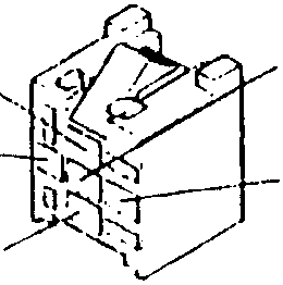
RELAYS:
In its simplest form, a relay is composed of a coil and a contact. When voltage is applied to the ends of the coil the contact closes.
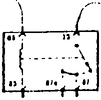
Normally the ends of the coil are identified as pins 85 and 86, while the terminals of the contact are pin 30 (from the power supply) and pin 87 towards the charge. There may also be two output pins towards the charge: 87a and 87b when the contact closes at the same time on both, and 87 and 87b when they close separately.
The contact can also be a switch and close itself on one pin (87a) at the same time as opening the other (87).
(For the different types of relay refer to the symbology table relative to the previous components).
To check a relay, connect pins 85 and 86 to a 12 V power source (the coil does not have a polarity and therefore the two pins are interchangeable) and using a Multimeter set to read ohms, measure the coil: when it is "excited" (between the ends of the coil there will be a difference in voltage of 12 V) the Multimeter should measure the continuity (0 Ω) between pin 30 and pin 87 (or 87a or 87b). When the coil is not excited, the Multimeter should show an open circuit (resistance ∞).
IN A RELAY SWITCH, THE CHECK WILL CONSIST OF THE PASSAGE FROM CONTINUITY TO OPEN CIRCUIT ON ONE PIN AND VICE-VERSA ON THE OTHER
One of the most common malfunctions affecting the relays is the "locking" of the contact. This can be immediately identified as the ohm signal does not vary when activating or deactivating the coil (always 0 Ω or always ∞).
NOTE: some relays have a built-in fuse: this though must be checked separately before checking the relay.
In other relays a resistance is placed in parallel to the activated circuit, in others a diode protects the excitation; in these cases the method of checking the operation of the relay does not differ from the method given above.
THERMOCONTACTS:
The thermal contacts change their state (circuit closed or open) when a certain temperature is reached.
NOTE: they can be N.C. (normally closed) or N.O. (normally open); in the diagrams they are shown at their rest position.
To check a thermocouple, remove it from the vehicle and connect the terminals to the Multimeter set to measure ohms.
Using suitable equipment (containers which can be heated and cooled) check that at the setting temperature of each thermocouple, the resistance varies from 0 Ω to ∞ or vice-versa.
SENSORS:
These are components of varying types which are in general similar to contacts (N.O. or N.C.), changing their state when a certain measured physical value varies (e.g. temperature, see thermocouples, or pressure etc.). For these components, the same rules apply as for checking the thermocouples.
Other sensors measure specific values and emit a signal which is proportional to these values. As each occasion arises, these will be indicated in the electrical charge diagram which if followed, makes it possible to identify the correct voltage or resistance values to be checked by the Multimeter.
RHEOSTATS:
Rheostats are variable resistances: when voltage (12 V) is applied to the main terminals, the output signal from the third terminal is varied by mechanical action (e.g. rotating a regulating wheel).
To check the correct operation, connect one of the prongs of a Multimeter set to measure ohms, to one of the main terminals and the other to the third terminal. By acting on the regulation wheel for example, the resistance should vary.
Parts & tools for this job For 1992 Alfa Romeo 155
- TOOLDigital multimeterSearch: automotive digital multimeter
- PARTAssorted fuse kitSearch: car fuse assortment kit
- TOOLWire crimper and connector kitSearch: wire crimper connector kit
Links open Amazon search results in a new tab. As an Amazon Associate I earn from qualifying purchases.