
Description
- Make
- Alfa Romeo
- Model
- 155 Factory Service Manual
- Year
- 1992–1998
- Section
- Description › Description
DESCRIPTION
The system is of the sealed type. The flow of coolant is forced by a centrifugal pump driven by the crankshaft through a V-type belt.
A thermostatic valve located on the rear side of the engine keeps the engine temperature at an optimum level. The thermostat opens when the coolant reaches a temperature of 87°C.
The radiator cools the liquid in the engine by dynamic air and by a two-speed cooling fan controlled by a thermal switch located on the radiator. An additional resistance and a relay select the higher fan speed if the temperature gets too high.
The expansion tank tops-up the cooling system if the coolant level falls and absorbs the changes in the volume of the coolant due to changes in temperature. The expansion tank also ensures that air is bled from the system. The cooling system also includes an engine coolant temperature sender for the indicator and a maximum temperature thermal switch for the warning lamp which comes on when the temperature of the liquid exceeds ~112°C.
A secondary pipe branches off from here and passes through the throttle valve body in order to heat it. It also serves to bleed off any air in the system thorough the expansion tank.
CAUTION The anti-freeze mixture is harmful to paintwork. All contact with painted surfaces should be avoided.
DRAINING THE HYDRAULIC SYSTEM
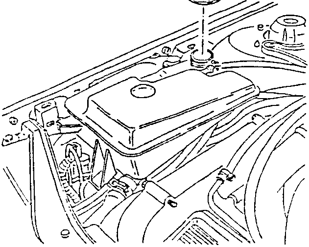
- Unscrew and remove the cap from the expansion tank.
CAUTION Never remove the cap from the expansion tank when the engine is warm!
SYSTEM OPERATION
After the liquid has cooled the engine it reaches the the thermostat group through the cylinder heads. If the temperature is below 87°C it is then directed to the pump through the engine coolant return longitudinal manifold located between the two cylinder heads. If the temperature is higher than this value, it is directed to the radiator through the opening in the thermostat.
After being cooled in the radiator, the coolant returns once again through the longitudinal manifold to the pump which channels it to the engine.
A union on the right-hand cylinder head receives the coolant through a supplementary channel and directs it to the heater by a main artery pipe.
Parts & tools for this job For 1992 Alfa Romeo 155
- PARTEngine gasket setSearch: Alfa Romeo 155 1992 engine gasket set
- TOOLTorque wrenchSearch: 3/8 inch torque wrench
- TOOLFeeler gauge setSearch: feeler gauge set
Links open Amazon search results in a new tab. As an Amazon Associate I earn from qualifying purchases.