
Pedal assembly - r.r
- Make
- Alfa Romeo
- Model
- Brera and Spider Factory Service Manual
- Year
- 2005–2010
- Section
- Hydraulic brake system › Pedal assembly - r.r
PEDAL ASSEMBLY - R.R
Removing
- Make sure that the ignition key is in the OFF position, then disconnect the battery terminal (-).
| Description | Connector | |
|---|---|---|
| Battery | See A001 BATTERY |
Op. 0010T84 COOLANT FOR AIR CONDITIONING SYSTEM - DEHYDRATE AND REPRESSURIZE
Op. 7210E36 R.R. FRONT SIDE DOOR
Op. 5010C30 CENTRAL AIR VENT IN DASHBOARD - R.R.
Op. 5010C12 WINDSCREEN DEMISTER DIFFUSER - R+R
Op. 5010D56 SOLAR SENSOR - R.R FOLLOWING ELECTRICAL SYSTEM CHECK
Op. 7040A44 LEFT DASHBOARD SIDE TRIM - R.R.
Op. 5580C18 AIR BAG MODULE - R+R
Op. 4110A10 STEERING WHEEL - R+R FOR REPLACEMENT OR CHECKS
Op. 7040A26 STEERING COLUMN TRIM - R+R
Op. 5560B10 CONTROL PANEL - R+R
Op. 7040A45 RIGHT DASHBOARD SIDE TRIM - R.R.
Op. 7040A31 DASHBOARD COMPARTMENT ASSEMBLY - R.R.
Op. 5580C22 AIR BAG MODULE - PASSENGER SIDE - R.R
Op. 7040A58 INSTRUMENT PANEL MOULDING - R+R
Op. 5580C26 PASSENGER AIR BAG DISABLING KEY LOCK BARREL/SWITCH - R.R.
Op. 5010C55 LOWER AIR DIFFUSER (ONE) LH OR RH - R.R
Op. 7040A65 CONSOLE SIDE CLOSING (ONE) - R.R.
Op. 5010C32
Op. 7040L20 TUNNEL COVER - R.R
Op. 5580C23 DRIVE SIDE KNEE PROTECTION AIR BAG MODULE R. R.
op. 7040A56
Op. 5040D18 AIR CONDITIONING CONTROL UNIT - R.R.
Op. 7040A10 DASHBOARD TRIM - R+R
Op. 7040L06 PASSENGER COMPARTMENT FLOOR RIGHT FRONT CARPET - R. R.
Op. 5010B70 SIDE CONNECTOR BRACKETS ONE, LH OR RH, BETWEEN AIR CONDITIONER CASING AND DUCT FOR R
(left and right).
Op. 5010B46 CENTRAL AIR DUCT TO REAR SEATS - R.R.
Op. 5050B34 WINDSCREEN WIPER ARM/S COMPLETE WITH BLADE - R+R
Op. 7025A64 ENGINE COMPARTMENT GASKET - R.R.
Op. 7210E22 R.R. WINDSCREEN BASE TRIM
Op. 5050B38 WINDSCREEN WIPER ASSEMBLY - R+R OR REPAIR
Op. 7040A89 REINFORCEMENT BRACKET BETWEEN DASHBOARD SUPPORTING CROSSMEMER AND BODYSHELL - R.R.
Op. 4110A30 SUPPORT WITH STEERING CONTROL SHAFTS - R+R
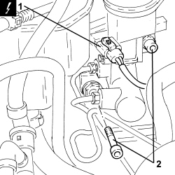
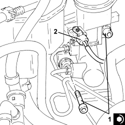
1. Disconnect the electrical connection from the brake fluid minimum level warning light switch.
| Description | Connector | |
|---|---|---|
| 1 | Brake fluid level sensor (switch) | See K025 BRAKE FLUID LEVEL SENSOR (SWITCH) |
2. Undo the bolts fixing the brake servo to the pedal assembly.
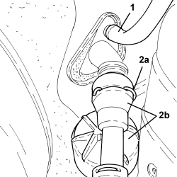
1. Disconnect the flexible pipe from the clutch reservoir to the master cylinder, master cylinder side.
Collect any brake-clutch fluid that comes out.
2. Lift the retaining clip (2a) and disconnect the clutch hydraulic circuit vibration damper (2b), clutch master cylinder side.
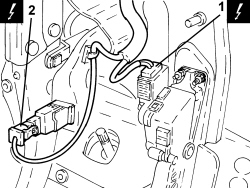
1. Disconnect the electrical connection from the accelerator pedal with built in potentiometer.
| Description | Connector | |
|---|---|---|
| 1 | Accelerator pedal potentiometer | See K055 ACCELERATOR PEDAL POTENTIOMETER |
2. Disconnect the electrical connection from the brake pedal switch.
| Description | Connector | |
|---|---|---|
| 2 | Brake pedal switch | See I030 BRAKE PEDAL SWITCH |
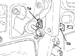
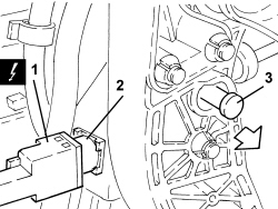
1. Remove the retaining clip (1a) and move back pin (1b) connecting the brake pedal to the brake servo.
2. Turn the switch on the brake pedal clockwise through 90° and remove.
1. Disconnect the electrical connection from the clutch pedal switch.
| Description | Connector | |
|---|---|---|
| 1 | Clutch pedal switch | See I031 CLUTCH PEDAL SWITCH |
2. Turn the clutch pedal switch clockwise through 90° and remove.
3. Withdraw the pin connectng the clutch pump to the pedal.
Replace the above pin whenever it is removed.
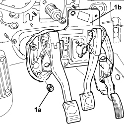
1. Undo the nuts (1a) and remove the pedal assembly (1b).
Refitting
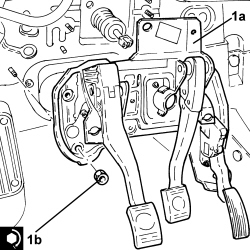
1. Position the pedal assembly (1a) in its housing and secure it by tightening the nuts (1b) to the recommended torque.
| Component | Fastening | dia | Value (daNm) | Validity |
|---|---|---|---|---|
| Pedal assembly | Nut | M8 | 2.2 ÷ 2.6 |
- Refit a new pin to connect the clutch pump to the pedal.
- Press the clutch pedal, then refit the cluch pedal switch and turn through 90° anticlockwise until it fits into place on the ridge.
- Release the clutch pedal and pull it backwards until it is at the end of its travel (rest position).
- Operate the clutch pedal through a full cycle to settle the switch.
- Connect the electrical connection to the clutch pedal switch.
- Refit the pin connecting the brake pedal to the brake servo and secure with the clip.
- Press the brake pedal, then refit the switch in its seat on the brake pedal and turn through 90° anticlockwise until it is fully home.
- Release the brake pedal.
- Connect the electrical connection to the brake pedal switch.
- Connect the electrical connection to the accelerator pedal with built in potentiometer.
- Fit the retaining clip fully, then fit the clutch hydraulic circuit vibration damper on the clutch master cylinder until the clip fastens.
- Connect the flexible pipe from the clutch reservoir to the master cylinder, master cylinder side.
1. Tighten the bolts fixing the brake servo to the pedal assembly to the recommended torque.
| Component | Fastening | dia | Value (daNm) | Validity |
|---|---|---|---|---|
| Brake servo | Bolt | M8 | 2.2 ÷ 2.6 |
2. Connect the electrical connection to the brake fluid minimum level warning light switch.
Op. 4110A30 SUPPORT WITH STEERING CONTROL SHAFTS - R+R
Op. 7040A89 REINFORCEMENT BRACKET BETWEEN DASHBOARD SUPPORTING CROSSMEMER AND BODYSHELL - R.R.
Op. 5050B38 WINDSCREEN WIPER ASSEMBLY - R+R OR REPAIR
Op. 7210E22 R.R. WINDSCREEN BASE TRIM
Op. 7025A64 ENGINE COMPARTMENT GASKET - R.R.
Op. 5050B34 WINDSCREEN WIPER ARM/S COMPLETE WITH BLADE - R+R
Op. 5010B46
Op. 5010B70
(left and right).
Op. 7040L06
Op. 7040A10 DASHBOARD TRIM - R+R
Op. 5040D18 AIR CONDITIONING CONTROL UNIT - R.R.
op. 7040A56
Op. 5580C23 DRIVE SIDE KNEE PROTECTION AIR BAG MODULE R. R.
Op. 7040L20 TUNNEL COVER - R.R
Op. 5580C22 AIR BAG MODULE - PASSENGER SIDE - R.R
Op. 5010C32
Op. 7040A65 CONSOLE SIDE CLOSING (ONE) - R.R.
Op. 5010C55 LOWER AIR DIFFUSER (ONE) LH OR RH - R.R
Op. 5580C26 PASSENGER AIR BAG DISABLING KEY LOCK BARREL/SWITCH - R.R.
Op. 7040A58 INSTRUMENT PANEL MOULDING - R+R
Op. 5580C22 AIR BAG MODULE - PASSENGER SIDE - R.R
Op. 7040A31 DASHBOARD COMPARTMENT ASSEMBLY - R.R.
Op. 7040A45 RIGHT DASHBOARD SIDE TRIM - R.R.
Op. 5560B10 CONTROL PANEL - R+R
Op. 7040A26 STEERING COLUMN TRIM - R+R
Op. 4110A10 STEERING WHEEL - R+R FOR REPLACEMENT OR CHECKS
Op. 5580C18 AIR BAG MODULE - R+R
Op. 7040A44 LEFT DASHBOARD SIDE TRIM - R.R.
Op. 5010D56 SOLAR SENSOR - R.R FOLLOWING ELECTRICAL SYSTEM CHECK
Op. 5010C12 WINDSCREEN DEMISTER DIFFUSER - R+R
Op. 5010C30 CENTRAL AIR VENT IN DASHBOARD - R.R.
Op. 7210E36 R.R. FRONT SIDE DOOR
Op. 0010T84 COOLANT FOR AIR CONDITIONING SYSTEM - DEHYDRATE AND REPRESSURIZE
Op. 0010T64 BRAKE AND/OR CLUTCH FLUID CHECK LEVEL AND TOP UP AS NECESSARY
Op. 0010T67 HYDRAULIC CLUTCH SYSTEM - BLEED AIR
- Connect the negative battery terminal.
Parts & tools for this job For 2005 Alfa Romeo Brera
- PARTBrake padsSearch: Alfa Romeo Brera 2005 brake pads
- TOOLBrake bleeder kitSearch: one man brake bleeder kit
- FLUIDBrake fluidSearch: brake fluid
Links open Amazon search results in a new tab. As an Amazon Associate I earn from qualifying purchases.