
Fuel supply pipe (one) - r.r.
- Make
- Alfa Romeo
- Model
- Brera and Spider Factory Service Manual
- Year
- 2005–2010
- Section
- Fuel tank and pipes › Fuel supply pipe (one) - r.r.
FUEL SUPPLY PIPE (ONE) - R.R.
Removing
Op. 4450B13 REAR WHEELS (TWO) - R.R
Op. 2720C10 DIFFERENCIAL UNIT - R.R.
Op. 2410A18 TRANSMISSION WITH JOINTS INCLUDED - R.R.
Op. 7050A20
Op. 1040A10 FUEL TANK - R + R AND DECANT FUEL
Op. 1040E22 FUEL PIPE PROTECTION - R.R
Op. 1072B50 AIR CHAMBER - R.R.
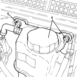
1. Undo the fixing nuts and move the engine coolant reservoir to one side.
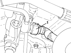
1. Disconnect the fuel supply pipe rapid connector, pressure pump rigid inlet pipe side.
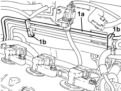
1. Release the rigid section of the fuel supply pipe (1a) from the fastening clips (1b).
- Undo the fastenings and remove the electrical connections protection.
1. Disconnect the electrical connection for the left head Lambda sensor catalyzer.
| Description | Connector | |
|---|---|---|
| 1 | Lambda sensor on catalyzer 2 | See K018 LAMBDA SENSOR ON CATALYZER - 2 |
2. Disconnect the electrical connection for the right head Lambda sensor catalyzer.
| Description | Connector | |
|---|---|---|
| 2 | Lambda sensor on catalyzer | See K017 LAMBDA SENSOR ON CATALYZER |
3. Undo the nuts (3a) and remove the catalyzer assembly (3b).
- Remove the metal gaskets.
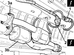
1. Undo the bolts and remove the front section of the exhaust from the left head precatalyzer.
- Remove the metal gasket.
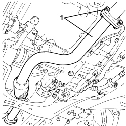
1. Release the fuel supply pipe from the underbody fastenings and remove it.
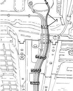
Refitting
- Place the fuel supply pipe in position, secure it to the bodyshell using the clips and connect it to the pressure pump rigid inlet pipe.
- Place the front section of the exhaust and the gasket in position and connect it to the precatalyzer using the bolts.
- Place the catalyzer assembly and gaskets in position and connect it to the two front exhaust pipes using the fixing nuts.
- Connect the electrical connections for the two Lambda sensors and fit the protection.
- Place the engine coolant reservoir on its bracket and secure it using the nuts.
Op. 1072B50 AIR CHAMBER - R.R.
Op. 1040E22 FUEL PIPE PROTECTION - R.R
Op. 1040A10 FUEL TANK - R + R AND DECANT FUEL
Op. 7050A20
Op. 2410A18 TRANSMISSION WITH JOINTS INCLUDED - R.R.
Op. 2720C10 DIFFERENCIAL UNIT - R.R.
Op. 4450B13 REAR WHEELS (TWO) - R.R
Removing
- Position the vehicle on a lift.
- Make sure that the ignition key is in the OFF position, then disconnect the battery terminal (-).
Op. 7050A20
Op. 1040A10 FUEL TANK - R + R AND DECANT FUEL
Op. 1040E22 FUEL PIPE PROTECTION - R.R
1. Release the fuel supply pipe from the underbody fastenings.
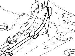
1. Disconnect the rapid connector for the fuel supply pipe from the three-way connector.
2. Undo the bolts (2a) and move the engine coolant supply reservoir (2b) aside.
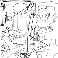
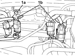
1. Undo the bolts (1a) and move the two electrical wiring mounting brackets (1b) aside.
- Release the fuel supply pipe from the fastenings on the engine compartment bulkhead and remove it.
Refitting
- Place the fuel supply pipe in its housing and secure it to the engine compartment bulkhead using the clips.
- Refit both electrical connecion brackets in their seats and secure with bolts.
- Fit the engine cooling reservoir in place and secure it using the bolts.
- Connect the rapid connector for the fuel supply pipe to the three-way connector.
- Fasten the fuel supply pipe using the underbody fastenings.
Op. 1040E22 FUEL PIPE PROTECTION - R.R
Op. 1040A10 FUEL TANK - R + R AND DECANT FUEL
Op. 7050A20
- Connect the negative battery terminal.
- Remove the vehicle from the lift.
Parts & tools for this job For 2005 Alfa Romeo Brera
- PARTEngine gasket setSearch: Alfa Romeo Brera 2005 engine gasket set
- TOOLTorque wrenchSearch: 3/8 inch torque wrench
- TOOLFeeler gauge setSearch: feeler gauge set
Links open Amazon search results in a new tab. As an Amazon Associate I earn from qualifying purchases.