
Headlamp/light cluster light beam - position
- Make
- Alfa Romeo
- Model
- GT Factory Service Manual
- Year
- 2003–2010
- Section
- Exterior lighting › Headlamp/light cluster light beam - position
HEADLAMP/LIGHT CLUSTER LIGHT BEAM - POSITION
Prepare the vehicle complete with spare wheel, tools, fluids, fuel reserve.
Check that the tyre inflation pressure is correct.
Place the vehicle on a flat surface, perpendicular to a screen with an opaque surface 10 metres away on which the following lines are traced.
1. V-V: vertical, corresponding to the trace of vehicle plane of symmetry.
2. C-C: traces of vertical planes passing through the reference centres of the light clusters.
3. HC-HC: horizontal corresponding to the height from the ground of the reference centres for the light clusters.
4. AC-AC: horizontal 10 cm below the line HC - HC.
5. Lines inclined by 15° as illustrated in the diagram.
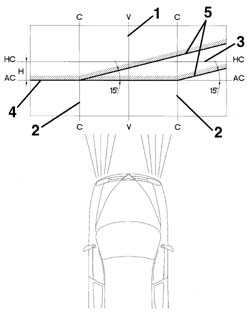
- Switch on the dipped headlamps.
- Vertical alignment: Adjust the vertical adjustment screw for the light cluster so that the horizontal section of the demarcation line between the dark zone and the area lit up by the light band is aligned with the line AC - AC traced on the screen.
- Horizontal alignment: Adjust the horizontal adjustment screw for the light cluster so that the point where the two horizontal and inclined demarcation lines cross with the point where lines C - C and AC - AC cross on the screen are aligned.
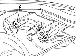
- Prepare the vehicle complete with spare wheel, tools, fluids, fuel reserve.
- Check that the tyre inflation pressure is correct.
- Place the vehicle on a flat surface, perpendicular to a screen with an opaque surface 10 metres away on which the following lines are traced.
- V-V: vertical, corresponding to the trace of vehicle plane of symmetry.
- C-C: traces of vertical planes passing through the reference centres of the light clusters.
- HC-HC: horizontal corresponding to the height from the ground of the reference centres for the light clusters.
- AC-AC: horizontal 10 cm below the line HC - HC.
- Lines inclined by 15° as illustrated in the diagram.
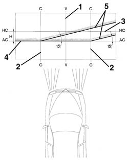
- Switch on the dipped headlamps.
1. Vertical alignment: Adjust the vertical adjustment screw for the light cluster so that the horizontal section of the demarcation line between the dark zone and the area lit up by the light band is aligned with the line AC - AC traced on the screen.
2. Horizontal alignment: Adjust the horizontal adjustment screw for the light cluster so that the point where the two horizontal and inclined demarcation lines cross with the point where lines C - C and AC - AC cross on the screen are aligned.
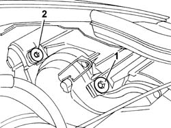
Parts & tools for this job For 2003 Alfa Romeo GT
- PARTReplacement bulbsSearch: Alfa Romeo GT 2003 bulbs
- TOOLDigital multimeterSearch: automotive digital multimeter
Links open Amazon search results in a new tab. As an Amazon Associate I earn from qualifying purchases.