
Front suspension beam - r r
- Make
- Alfa Romeo
- Model
- GT Factory Service Manual
- Year
- 2003–2010
- Section
- Front suspension › Front suspension beam - r r
FRONT SUSPENSION BEAM - R R
Removing
Position the vehicle on a lift.
Proceed with the removal
Op. 1016A40 IGNITION COIL COVER ON CYLINDER HEAD- R+R.
Drain the air conditioning refrigerant circuit
Op. 0010T84 COOLANT FOR AIR CONDITIONING SYSTEM DEHYDRATE AND RECHARGE.
Proceed with the removal
Op. 4450B12 FRONT OR REAR WHEELS (TWO) - R+R.
Proceed with the removal
Op. 7055B65 ENGINGE BAY DUSTGUARD PROTECTION IN LEFT FRONT WHEEL ARCH R R.
Proceed with the removal
Op. 7055B66 ENGINE COMPARTMENT DUST SHIELD PROTECTION IN RIGHT FRONT WHEEL ARCH - R.R..
Proceed with the removal
Op. 7055B54 UNDER-ENGINE GUARD - R R.
Proceed with the removal
Op. 5040A20 AIR CONDITIONER COMPRESSOR - R+R - INCLUDES FLUID LEVEL CHECK AND TOP UP IF NECESSARY.
Proceed with the removal
Op. 5040A26 COMPRESSOR MOUNT - R R.
Proceed with the removal
Op. 1076A48 CATALYTIC CONVERTER HEAT SHIELD - R R.
Proceed with the removal
Op. 1080B62 CATALYTIC CONVERTER - R + R.
Proceed with the removal
Op. 1076B18 RIGID SECTION OF EXHAUST PIPE BETWEEN CATALYTIC CONVERTER AND SILENCER - R + R.
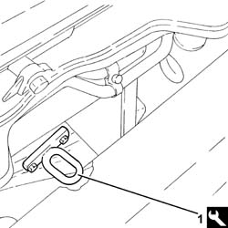
1. Fit the tool for safely supporting the power unit on the engine block as illustrated.
| Description | Code | |
|---|---|---|
| 1 | Support | 1.860.625.000 |
1. Fit a suitable bracket for safely supporting the power unit on the intake manifold.
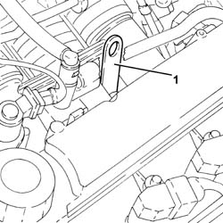
Fit the tool complete with support mountings.
| Description | Code | |
|---|---|---|
| Crossmember | 1.820.581.000 |
| Description | Code | |
|---|---|---|
| Support mountings | 1.870.650.000 |
Fit the tools and connect them using the rods to the brackets fitted previously.
| Description | Code | |
|---|---|---|
| Crossmember | 1.860.851.003 |
| Description | Code | |
|---|---|---|
| Vertical support | 1.870.748.000 |
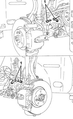
1. Undo the bolts fixing the driveshafts to the differential internal driveshaft/intermediate driveshaft.
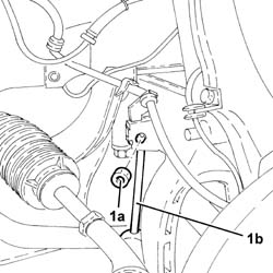
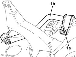
1. Undo the nuts (1a) and disconnect the front suspension anti-roll bar joints (1b) from the front shock absorber forks.
1. Undo the bolts fixing the front shock absorber forks to the lower track control arms. 2. Undo the nuts fixing the front suspension lower track control arms to the steering knuckles.
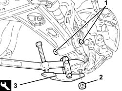
3. Using the tool disconnect the front suspension lower track control arms from the steering knuckles.
| Description | Code | |
|---|---|---|
| 3 | Extractor | 1.821.169.000 |
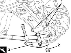
Proceed with the removal
Op. 1008A44 REAR RIGID MOUNT - R R.
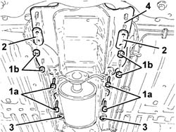
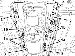
1. Undo the front bolts (1a) and nuts (1b) fixing the gearbox control support.
2. Keep the plates.
3. Loosen the rear bolts fixing the gearbox control lever support.
4. Lower the gearbox control support at the front as necessary.
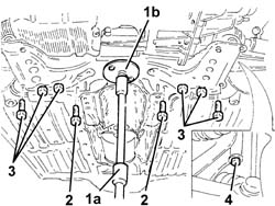
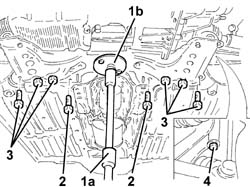
1. Support the front suspension crossmember using the hydraulic jack (1a) fitted with a suitable flange (1b).
2. Undo the bolts fixing the power assisted steering box to the front suspension crossmember.
3. Undo the rear bolts fixing the front suspension crossmember to the bodyshell.
4. Undo the side bolts fixing the front suspension crossmember to the bodyshell.
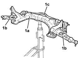
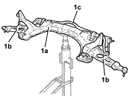
1. Lower the hydraulic jack slowly and remove the front suspension crossmember (1a) complete with lower track control arms (1b) and anti-roll bar (1c).
1. At the bench, undo the bolts (1a) and remove the anti-roll bar (1b) complete with joints.
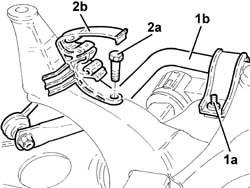
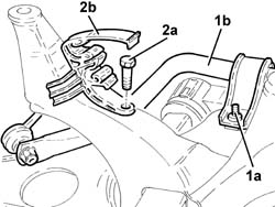
2. Undo the bolt (2a) and remove the power assisted steering system pipe mounting bracket (2b).
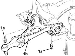
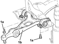
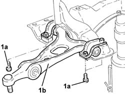
1. Undo the bolts (1a) and remove the front suspension lower track control arms (1b).
Refitting
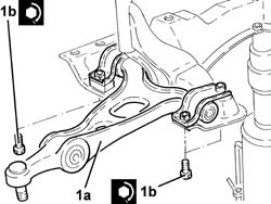
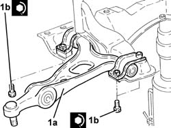
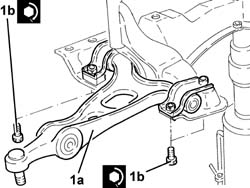
1. Place the front suspension lower track control arms (1a) in their housings and secure them to the front suspension crossmember by tightening the bolts (1b) to the recommended torque.
| Fastening | Component | Ø | Value (daNm) | |
|---|---|---|---|---|
| 1b | Bolt | LOWER FRONT TRACK CONTROL ARMS | M10 | (Front suspension crossmember side) 7.1 - 7.9 |
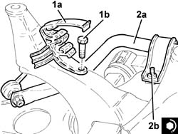
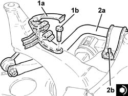
1. Place the power assisted steering system pipe mounting bracket (1a) in position and fasten it to the front suspension crossmember using the bolt (1b).
2. Place the anti-roll bar (2a) complete with joints in its housing and secure it to the front suspension crossmember by tightening the bolts (2b) to the recommended torque.
| Fastening | Component | Ø | Value (daNm) | |
|---|---|---|---|---|
| 2b | Bolt | FRONT ANTI-ROLL BAR | M8 | (Front suspension crossmember side) 3.6 - 4.4 |
Using the hydraulic jack fitted with a suitable flange, place the front suspension crossmember back in its housing complete with lower track control arms and anti-roll bar.
1. Tighten the side bolts fixing the front suspension crossmember to the bodyshell to the recommended torque.
| Fastening | Component | Ø | Value (daNm) | |
|---|---|---|---|---|
| 1 | Side bolt | FRONT SUSPENSION CROSSMEMBER | M12 | (Bodyshell side) 10.8 - 13.2 |
2. Tighten the rear bolts fixing the front suspension crossmember to the bodyshell to the recommended torque.
| Fastening | Component | Ø | Value (daNm) | |
|---|---|---|---|---|
| 2 | Rear bolt | FRONT SUSPENSION CROSSMEMBER | M12 | (Bodyshell side) 10.8 - 13.2 |
| Fastening | Component | Ø | Value (daNm) | |
|---|---|---|---|---|
| 2 | Rear bolt | FRONT SUSPENSION CROSSMEMBER | M10 | (Bodyshell side) 8.1 - 9.9 |
3. Tighten the bolts fixing the power assisted steering box to the rear suspension crossmember to the recommended torque.
| Fastening | Component | Ø | Value (daNm) | |
|---|---|---|---|---|
| 3 | Bolt | POWER STEERING BOX | M14 | (Front suspension crossmember side) 11.7 - 14.3 |
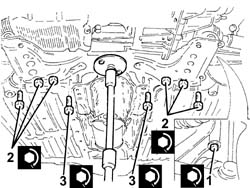
Remove the hydraulic jack fitted with a support tool from the front suspension crossmember.
Place the manual gearbox control lever support back in its housing and secure it using the bolts and the nuts.
Proceed with the refitting
Op. 1008A44 REAR RIGID MOUNT - R R.
Connect the front suspension lower track control arms to the steering knuckles.
1. Connect the front suspension lower track control arms to the steering knuckles and fasten them by tightening the nuts to the recomended torque.
| Fastening | Component | Ø | Value (daNm) | |
|---|---|---|---|---|
| 1 | Nut | INJECTORS(DIESEL) | M8 | (Cylinder head side) 2.7 -4.0 |
2. Tighten the bolts fixing the front shock absorber forks to the lower track control arms to the recommended torque.
| Fastening | Component | Ø | Value (daNm) | |
|---|---|---|---|---|
| 2 | Bolt | FRONT DAMPER FORK ON WISHBONE | M12 | (Lower track control arm side) 10.8 - 13.2 |
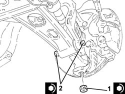
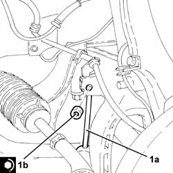
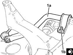
1. Connect the front suspension anti-roll bar joints (1a) to the front shock absorber forks and secure them tightening the nuts (1b) to the recommended torque.
| Fastening | Component | Ø | Value (daNm) | |
|---|---|---|---|---|
| 1b | Nut | FRONT ANTI-ROLL BAR JOINTS | M10 | (Front shock absorber fork side) 4.1 - 5.0 |
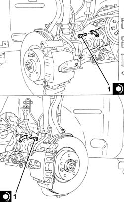
1. Tighten the bolts fixing the driveshafts to the differential internal driveshaft/intermediate driveshaft to the recommended torque.
| Fastening | Component | Ø | Value (daNm) | |
|---|---|---|---|---|
| 1 | Bolt | DRIVESHAFT | M8 | (Differential internal driveshaft/intermediate driveshaft side) 3.6 - 4.4 |
Remove the tools used for supporting the power unit safely.
Proceed with the refitting
Op. 1076B18 RIGID SECTION OF EXHAUST PIPE BETWEEN CATALYTIC CONVERTER AND SILENCER - R + R.
Proceed with the refitting
Op. 1080B62 CATALYTIC CONVERTER - R + R.
Proceed with the refitting
Op. 1076A48 CATALYTIC CONVERTER HEAT SHIELD - R R.
Proceed with the refitting
Op. 5040A26 COMPRESSOR MOUNT - R R.
Proceed with the refitting
Op. 5040A20 AIR CONDITIONER COMPRESSOR - R+R - INCLUDES FLUID LEVEL CHECK AND TOP UP IF NECESSARY.
Proceed with the refitting
Op. 7055B54 UNDER-ENGINE GUARD - R R.
Proceed with the refitting
Op. 7055B66 ENGINE COMPARTMENT DUST SHIELD PROTECTION IN RIGHT FRONT WHEEL ARCH - R.R..
Proceed with the refitting
Op. 7055B65 ENGINGE BAY DUSTGUARD PROTECTION IN LEFT FRONT WHEEL ARCH R R.
Proceed with the refitting
Op. 4450B12 FRONT OR REAR WHEELS (TWO) - R+R.
Refill the air conditioning refrigerant circuit
Op. 0010T84 COOLANT FOR AIR CONDITIONING SYSTEM DEHYDRATE AND RECHARGE.
Proceed with the refitting
Op. 1016A40 IGNITION COIL COVER ON CYLINDER HEAD- R+R.
Remove the vehicle from the lift.
Proceed with the refitting
Removing
Position the vehicle on a lift.
Proceed with the removal
Op. 7055B54 UNDER-ENGINE GUARD - R R.
Proceed with the removal
Op. 1076B82 LEFT EXHASUST PIPE BETWEEN CATALYTIC PRECONVERTER AND CONVERTER R R.
Proceed with the removal
Op. 1076B84 RIGHT EXHAUST PIPE BETWEEN CARALYTIC PRECONVERTER AND CONVERTER R R.
Proceed with the removal
Op. 4450B12 FRONT OR REAR WHEELS (TWO) - R+R.
Proceed with the removal
Op. 7055B65 ENGINGE BAY DUSTGUARD PROTECTION IN LEFT FRONT WHEEL ARCH R R.
Proceed with the removal
Op. 7055B66 ENGINE COMPARTMENT DUST SHIELD PROTECTION IN RIGHT FRONT WHEEL ARCH - R.R..
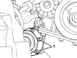
1. Undo the bolts fixing the right driveshaft to the intermediate shaft.
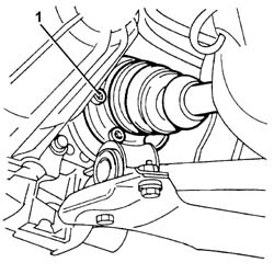
1. Undo the bolts fixing the left driveshaft to the differential internal shaft.
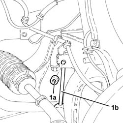
1. Undo the nuts (1a) and disconnect the front suspension anti-roll bar joints (1b) from the front shock absorber forks.
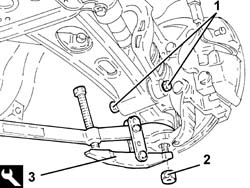
1. Undo the bolts fixing the front shock absorber forks to the lower track control arms. 2. Undo the nuts fixing the front suspension lower track control arms to the steering knuckles.
3. Using the tool disconnect the front suspension lower track control arms from the steering knuckles.
| Description | Code | |
|---|---|---|
| 3 | Extractor | 1.821.169.000 |
Proceed with the removal
Op. 1008A44 REAR RIGID MOUNT - R R.
Proceed with the removal
Op. 1008B20 POWER UNIT INTERMEDIATE MOUNT FLEXIBLE BLOCK - REPLACE.
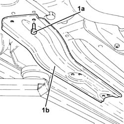
1. Undo the bolts (1a) and remove the underbody reinforcements (1b).
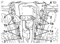
1. Undo the front bolts (1a) and nuts (1b) fixing the gearbox control support.
2. Keep the plates.
3. Loosen the rear bolts fixing the gearbox control lever support.
4. Lower the gearbox hand control support at the front.
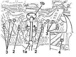
1. Position a hydraulic jack (1a) fitted with a suitable tool (1b) for supporting the front suspension crossmember.
2. Undo the bolts fixing the power assisted steering box to the front suspension crossmember.
3. Undo the rear bolts fixing the front suspension crossmember to the bodyshell.
4. Undo the side bolts fixing the front suspension crossmember to the bodyshell.
Release the power assisted steering pipes from the bracket on the front suspension crossmember.
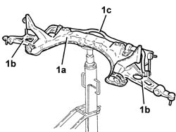
1. Lower the hydraulic jack slowly and remove the front suspension crossmember (1a) complete with lower track control arms (1b) and anti-roll bar (1c).
1. At the bench, undo the bolts (1a) and remove the anti-roll bar (1b) complete with joints.
1. Undo the bolts (1a) and remove the front suspension lower track control arms (1b).
Refitting
1. Place the front suspension lower track control arms (1a) in their housings and secure them to the front suspension crossmember by tightening the bolts (1b) to the recommended torque.
| Fastening | Component | Ø | Value (daNm) | |
|---|---|---|---|---|
| 1b | Bolt | LOWER FRONT TRACK CONTROL ARMS | M10 | (Front suspension crossmember side) 7.1 - 7.9 |
1. Place the anti-roll bar (1a) complete with joints in its housing and secure it to the front suspension crossmember by tightening the bolts (1b) to the recommended torque.
| Fastening | Component | Ø | Value (daNm) | |
|---|---|---|---|---|
| 1b | Bolt | FRONT ANTI-ROLL BAR | M8 | (Front suspension crossmember side) 3.6 - 4.4 |
Using the hydraulic jack fitted with a support tool, place the front suspension crossmember back in its housing complete with lower track control arms and anti-roll bar.
Fasten the power assisted steering pipes to the bracket on the front suspension crossmember.
1. Tighten the side bolts fixing the front suspension crossmember to the bodyshell to the recommended torque.
| Fastening | Component | Ø | Value (daNm) | |
|---|---|---|---|---|
| 1 | Side bolt | FRONT SUSPENSION CROSSMEMBER | M12 | (Bodyshell side) 10.8 - 13.2 |
2. Tighten the rear bolts fixing the front suspension crossmember to the bodyshell to the recommended torque.
| Fastening | Component | Ø | Value (daNm) | |
|---|---|---|---|---|
| 2 | Rear bolt | FRONT SUSPENSION CROSSMEMBER | M12 | (Bodyshell side) 10.8 - 13.2 |
| Fastening | Component | Ø | Value (daNm) | |
|---|---|---|---|---|
| 2 | Rear bolt | FRONT SUSPENSION CROSSMEMBER | M10 | (Bodyshell side) 8.1 - 9.9 |
3. Tighten the bolts fixing the power assisted steering box to the rear suspension crossmember to the recommended torque.
| Fastening | Component | Ø | Value (daNm) | |
|---|---|---|---|---|
| 3 | Bolt | POWER STEERING BOX | M14 | (Front suspension crossmember side) 11.7 - 14.3 |
4. Remove the hydraulic jack (4a) fitted with a suitable flange (4) for supporting the front suspension crossmember.
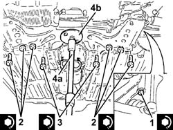
Remove the hydraulic jack fitted with a support tool from the front suspension crossmember.
Place the manual gearbox control lever support back in its housing and secure it using the bolts and the nuts.
Place the underbody reinforcements in position and secure them using the bolts.
Proceed with the refitting
Op. 1008B20 POWER UNIT INTERMEDIATE MOUNT FLEXIBLE BLOCK - REPLACE.
Proceed with the refitting
Op. 1008A44 REAR RIGID MOUNT - R R.
1. Connect the front suspension lower track control arms to the steering knuckles and fasten them by tightening the nuts to the recomended torque.
| Fastening | Component | Ø | Value (daNm) | |
|---|---|---|---|---|
| 1 | Nut | INJECTORS(DIESEL) | M8 | (Cylinder head side) 2.7 -4.0 |
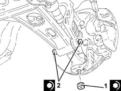
2. Tighten the bolts fixing the front shock absorber forks to the lower track control arms to the recommended torque.
| Fastening | Component | Ø | Value (daNm) | |
|---|---|---|---|---|
| 2 | Bolt | FRONT DAMPER FORK ON WISHBONE | M12 | (Lower track control arm side) 10.8 - 13.2 |
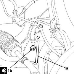
1. Connect the front suspension anti-roll bar joints (1a) to the front shock absorber forks and secure them tightening the nuts (1b) to the recommended torque.
| Fastening | Component | Ø | Value (daNm) | |
|---|---|---|---|---|
| 1b | Nut | FRONT ANTI-ROLL BAR JOINTS | M10 | (Front shock absorber fork side) 4.1 - 5.0 |
1. Tighten the bolts fixing the left driveshaft to the differential internal shaft to the recommended torque.
| Fastening | Component | Ø | Value (daNm) | |
|---|---|---|---|---|
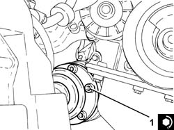
| 1 |
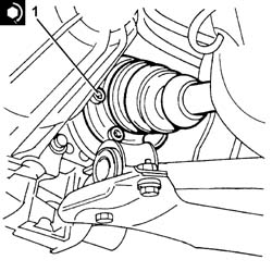
1. Tighten the bolts fixing the right driveshaft to the intermediate driveshaft to the recommended torque.
| Fastening | Component | Ø | Value (daNm) | |
|---|---|---|---|---|
| 1 |
Proceed with the refitting
Op. 7055B66 ENGINE COMPARTMENT DUST SHIELD PROTECTION IN RIGHT FRONT WHEEL ARCH - R.R..
Proceed with the refitting
Op. 7055B65 ENGINGE BAY DUSTGUARD PROTECTION IN LEFT FRONT WHEEL ARCH R R.
Proceed with the refitting
Op. 4450B12 FRONT OR REAR WHEELS (TWO) - R+R.
Proceed with the refitting
Op. 1076B84 RIGHT EXHAUST PIPE BETWEEN CARALYTIC PRECONVERTER AND CONVERTER R R.
Proceed with the refitting
Op. 1076B82 LEFT EXHASUST PIPE BETWEEN CATALYTIC PRECONVERTER AND CONVERTER R R.
Proceed with the refitting
Op. 7055B54 UNDER-ENGINE GUARD - R R.
Remove the vehicle from the lift.
Removing
Position the vehicle on a lift.
Proceed with removal - 1016A10 SOUNDPROOFING COVER - R&R.
Proceed with the removal
Op. 7055B54 UNDER-ENGINE GUARD - R R.
Proceed with the removal
Op. 1088D24 RIGID PIPE FOR COOLANT INLET TO WATER PUMP - R + R.
Proceed with the removal
Op. 1076B70 EXHAUST PIPE BETWEEN PRE-CATALYTIC CONVERTER AND CATALYTIC CONVERTER - R R.
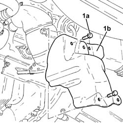
1. Undo the bolts (1a) and remove the exhaust manifold lower heat shield (1b).
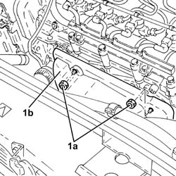
1. Undo the nuts (1a) and remove the exhaust manifold upper heat shield (1b).
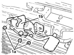
1. Undo the nuts (1a) and move the bonnet lock (1b) sideways without disconnect the bonnet release cable.
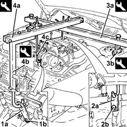
1. Fit the bracket (1a) on the exhaust manifold and secure it using the nut (1b).
2. Fit the bracket (2a) on the crankcase sump and secure it using the bolt (2b).
3. Fit the tool (3a) complete with support mountings (3b).
| Description | Code | |
|---|---|---|
| 3a | Crossmember | 1.820.581.000 |
| Description | Code | |
|---|---|---|
| 3b | Support mountings | 1.870.650.000 |
4. Fit the tools (4a) and (4b), then connect them to the brackets fitted previously using the rods (4c).
| Description | Code | |
|---|---|---|
| 4a | Crossmember | 1.860.851.003 |
| Description | Code | |
|---|---|---|
| 4b | Vertical support | 1.870.748.000 |
Proceed with the removal
Op. 4450B12 FRONT OR REAR WHEELS (TWO) - R+R.
Proceed with the removal
Op. 7055B65 ENGINGE BAY DUSTGUARD PROTECTION IN LEFT FRONT WHEEL ARCH R R.
Proceed with the removal
Op. 7055B66 ENGINE COMPARTMENT DUST SHIELD PROTECTION IN RIGHT FRONT WHEEL ARCH - R.R..
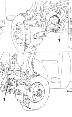
1. Loosen the bands fastening the driveshaft boots to the intermediate driveshaft/differential internal driveshaft.
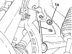
1. Undo the nuts (1a) and disconnect the front suspension anti-roll bar joints (1b) from the front shock absorber forks.
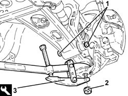
1. Undo the bolts fixing the front shock absorber forks to the lower track control arms. 2. Undo the nuts fixing the front suspension lower track control arms to the steering knuckles.
3. Using the tool disconnect the front suspension lower track control arms from the steering knuckles.
| Description | Code | |
|---|---|---|
| 3 | Extractor | 1.821.169.000 |
Proceed with the removal
Op. 1008A44 REAR RIGID MOUNT - R R.
Undo the bolts and remove the flexible mounting for the power unit rear support.
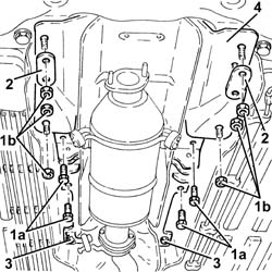
1. Undo the front bolts (1a) and nuts (1b) fixing the gearbox control support.
2. Keep the plates.
3. Loosen the rear bolts fixing the gearbox control lever support.
4. Lower the gearbox control support at the front as necessary.
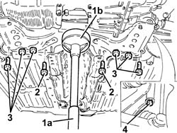
1. Position a hydraulic jack (1a) fitted with a suitable tool (1b) for supporting the front suspension crossmember.
2. Undo the bolts fixing the power assisted steering box to the front suspension crossmember.
3. Undo the rear bolts fixing the front suspension crossmember to the bodyshell.
4. Undo the side bolts fixing the front suspension crossmember to the bodyshell.
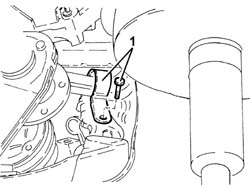
1. Release the power assisted steering pipes from the bracket on the front suspension crossmember.
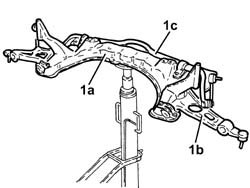
1. Lower the hydraulic jack slowly and remove the front suspension crossmember (1a) complete with lower track control arms (1b) and anti-roll bar (1c).
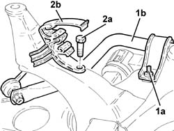
1. At the bench, undo the bolts (1a) and remove the anti-roll bar (1b) complete with joints.
2. Undo the bolt (2a) and remove the power assisted steering system pipe mounting bracket (2b).
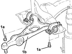
1. Undo the bolts (1a) and remove the front suspension lower track control arms (1b).
Refitting
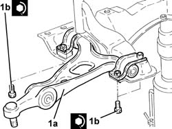
1. Place the front suspension lower track control arms (1a) in their housings and secure them to the front suspension crossmember by tightening the bolts (1b) to the recommended torque.
| Fastening | Component | Ø | Value (daNm) | |
|---|---|---|---|---|
| 1b | Bolt | LOWER FRONT TRACK CONTROL ARMS | M10 | (Front suspension crossmember side) 7.1 - 7.9 |
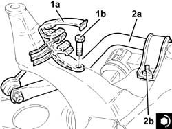
1. Place the power assisted steering system pipe mounting bracket (1a) in position and fasten it to the front suspension crossmember using the bolt (1b).
2. Place the anti-roll bar (2a) complete with joints in its housing and secure it to the front suspension crossmember by tightening the bolts (2b) to the recommended torque.
| Fastening | Component | Ø | Value (daNm) | |
|---|---|---|---|---|
| 2b | Bolt | FRONT ANTI-ROLL BAR | M8 | (Front suspension crossmember side) 3.6 - 4.4 |
Using the hydraulic jack fitted with a support tool, place the front suspension crossmember back in its housing complete with lower track control arms and anti-roll bar.
Fasten the power assisted steering pipes to the bracket on the front suspension crossmember.
1. Tighten the side bolts fixing the front suspension crossmember to the bodyshell to the recommended torque.
| Fastening | Component | Ø | Value (daNm) | |
|---|---|---|---|---|
| 1 | Side bolt | FRONT SUSPENSION CROSSMEMBER | M12 | (Bodyshell side) 10.8 - 13.2 |
2. Tighten the rear bolts fixing the front suspension crossmember to the bodyshell to the recommended torque.
| Fastening | Component | Ø | Value (daNm) | |
|---|---|---|---|---|
| 2 | Rear bolt | FRONT SUSPENSION CROSSMEMBER | M12 | (Bodyshell side) 10.8 - 13.2 |
| Fastening | Component | Ø | Value (daNm) | |
|---|---|---|---|---|
| 2 | Rear bolt | FRONT SUSPENSION CROSSMEMBER | M10 | (Bodyshell side) 8.1 - 9.9 |
3. Tighten the bolts fixing the power assisted steering box to the rear suspension crossmember to the recommended torque.
| Fastening | Component | Ø | Value (daNm) | |
|---|---|---|---|---|
| 3 | Bolt | POWER STEERING BOX | M14 | (Front suspension crossmember side) 11.7 - 14.3 |
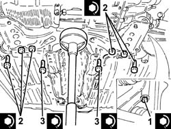
Remove the hydraulic jack fitted with a support tool from the front suspension crossmember.
Place the manual gearbox control lever support back in its housing and secure it using the bolts and the nuts.
Place the power unit rear support flexible mounting in its housing and secure it to the crossmember tightening the bolts to the recommended torque.
| Fastening | Component | Ø | Value (daNm) | |
|---|---|---|---|---|
| Bolt | INTERM RUBBER MOUNT | M8 | (Front suspension crossmember side) 3.2 - 3.9 |
Proceed with the refitting
Op. 1008A44 REAR RIGID MOUNT - R R.
1. Connect the front suspension lower track control arms to the steering knuckles and fasten them by tightening the nuts to the recomended torque.
| Fastening | Component | Ø | Value (daNm) | |
|---|---|---|---|---|
| 1 | Nut | INJECTORS(DIESEL) | M8 | (Cylinder head side) 2.7 -4.0 |
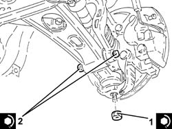
2. Tighten the bolts fixing the front shock absorber forks to the lower track control arms to the recommended torque.
| Fastening | Component | Ø | Value (daNm) | |
|---|---|---|---|---|
| 2 | Bolt | FRONT DAMPER FORK ON WISHBONE | M12 | (Lower track control arm side) 10.8 - 13.2 |
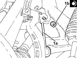
1. Connect the front suspension anti-roll bar joints (1a) to the front shock absorber forks and secure them tightening the nuts (1b) to the recommended torque.
| Fastening | Component | Ø | Value (daNm) | |
|---|---|---|---|---|
| 1b | Nut | FRONT ANTI-ROLL BAR JOINTS | M10 | (Front shock absorber fork side) 4.1 - 5.0 |
Tighten the bands fastening the driveshaft boots to the intermediate driveshaft/differential internal driveshaft.
Proceed with the refitting
Op. 7055B66 ENGINE COMPARTMENT DUST SHIELD PROTECTION IN RIGHT FRONT WHEEL ARCH - R.R..
Proceed with the refitting
Op. 7055B65 ENGINGE BAY DUSTGUARD PROTECTION IN LEFT FRONT WHEEL ARCH R R.
Proceed with the refitting
Op. 4450B12 FRONT OR REAR WHEELS (TWO) - R+R.
Remove the tools used for supporting the power unit safely.
Place the bonnet lock in position and secure it using the nuts.
Place the exhaust manifold upper heat shield in its housing, then secure it using the nuts.
Place the exhaust manifold lower heat shield in its housing and secure it using the bolts.
Proceed with the refitting
Op. 1076B70 EXHAUST PIPE BETWEEN PRE-CATALYTIC CONVERTER AND CATALYTIC CONVERTER - R R.
Proceed with the refitting
Op. 1088D24 RIGID PIPE FOR COOLANT INLET TO WATER PUMP - R + R.
Proceed with the refitting
Op. 7055B54 UNDER-ENGINE GUARD - R R.
Refill the engine cooling system
Op. 0010T20 COOLANT CHECK DENSITY AND TOP UP IF NECESSARY.
Proceed with refitting - 1016A10 SOUNDPROOFING COVER - R&R.
Remove the vehicle from the lift.
Proceed with the refitting
Removing
- Position the vehicle on a lift.
- Op. 1016A40 IGNITION COIL COVER ON CYLINDER HEAD- R+R
- Op. 4450B12 FRONT OR REAR WHEELS (TWO) - R+R
- Op. 7055B65 ENGINGE BAY DUSTGUARD PROTECTION IN LEFT FRONT WHEEL ARCH R R
- Op. 7055B66 ENGINE COMPARTMENT DUST SHIELD PROTECTION IN RIGHT FRONT WHEEL ARCH - R.R.
- Op. 7055B54 UNDER-ENGINE GUARD - R R
- Op. 1072C44 EXHAUST MANIFOLD HEAT SHIELD ON BULKHEAD - R+R
- Op. 1080B40 CATALYTIC PRE-CONVERTER - R R
- Undo the nuts (1a) and move the bonnet lock (1b) sideways without disconnect the bonnet release cable.
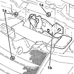
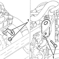
- Fit two suitable brackets on the engine for safely supporting the power unit as illustrated.
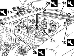
1. Fit the tool (1a) complete with mountings (1b).
| Description | Code | |
|---|---|---|
| 1a | Crossmember | 1.820.581.000 |
| Description | Code | |
|---|---|---|
| 1b | Support mountings | 1.870.650.000 |
2. Fit the tools (2a) and (2b), then connect them to the brackets fitted previously using the rods (2c).
| Description | Code | |
|---|---|---|
| 2a | Crossmember | 1.860.851.003 |
| Description | Code | |
|---|---|---|
| 2b | Vertical support | 1.870.748.000 |
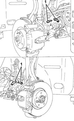
- Undo the bolts fixing the driveshafts to the differential internal driveshaft/intermediate driveshaft.
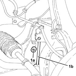
- Undo the nuts (1a) and disconnect the front suspension anti-roll bar joints (1b) from the front shock absorber forks.
- Undo the bolts fixing the front shock absorber forks to the lower track control arms.
- Undo the nuts fixing the front suspension lower track control arms to the steering knuckles.
- Using the tool disconnect the front suspension lower track control arms from the steering knuckles.
| Description | Code | |
|---|---|---|
| 3 | Extractor | 1.821.169.000 |
- Undo the front bolts (1a) and nuts (1b) fixing the gearbox control support.
- Keep the plates.
- Loosen the rear bolts fixing the gearbox control lever support.
- Lower the gearbox control support at the front as necessary.
- Support the front suspension crossmember using the hydraulic jack (1a) fitted with a suitable flange (1b).
- Undo the bolts fixing the power assisted steering box to the front suspension crossmember.
- Undo the rear bolts fixing the front suspension crossmember to the bodyshell.
- Undo the side bolts fixing the front suspension crossmember to the bodyshell.
- Lower the hydraulic jack slowly and remove the front suspension crossmember (1a) complete with lower track control arms (1b) and anti-roll bar (1c).
- At the bench, undo the bolts (1a) and remove the anti-roll bar (1b) complete with joints.
- Undo the bolt (2a) and remove the power assisted steering system pipe mounting bracket (2b).
- Undo the bolts (1a) and remove the front suspension lower track control arms (1b).
Refitting
- Place the front suspension lower track control arms (1a) in their housings and secure them to the front suspension crossmember by tightening the bolts (1b) to the recommended torque.
| Fastening | Component | Ø | Value (daNm) | |
|---|---|---|---|---|
| 1b | Bolt | LOWER FRONT TRACK CONTROL ARMS | M10 | (Front suspension crossmember side) 7.1 - 7.9 |
- Place the power assisted steering system pipe mounting bracket (1a) in position and fasten it to the front suspension crossmember using the bolt (1b).
- Place the anti-roll bar (2a) complete with joints in its housing and secure it to the front suspension crossmember by tightening the bolts (2b) to the recommended torque.
| Fastening | Component | Ø | Value (daNm) | |
|---|---|---|---|---|
| 2b | Bolt | FRONT ANTI-ROLL BAR | M8 | (Front suspension crossmember side) 3.6 - 4.4 |
- Using the hydraulic jack fitted with a suitable flange, place the front suspension crossmember back in its housing complete with lower track control arms and anti-roll bar.
1. Tighten the side bolts fixing the front suspension crossmember to the bodyshell to the recommended torque.
| Fastening | Component | Ø | Value (daNm) | |
|---|---|---|---|---|
| 1 | Side bolt | FRONT SUSPENSION CROSSMEMBER | M12 | (Bodyshell side) 10.8 - 13.2 |
2. Tighten the rear bolts fixing the front suspension crossmember to the bodyshell to the recommended torque.
| Fastening | Component | Ø | Value (daNm) | |
|---|---|---|---|---|
| 2 | Rear bolt | FRONT SUSPENSION CROSSMEMBER | M12 | (Bodyshell side) 10.8 - 13.2 |
| Fastening | Component | Ø | Value (daNm) | |
|---|---|---|---|---|
| 2 | Rear bolt | FRONT SUSPENSION CROSSMEMBER | M10 | (Bodyshell side) 8.1 - 9.9 |
3. Tighten the bolts fixing the power assisted steering box to the rear suspension crossmember to the recommended torque.
| Fastening | Component | Ø | Value (daNm) | |
|---|---|---|---|---|
| 3 | Bolt | POWER STEERING BOX | M14 | (Front suspension crossmember side) 11.7 - 14.3 |
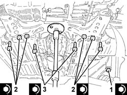
- Remove the hydraulic jack fitted with a support flange from the front suspension crossmember.
- Place the manual gearbox control lever support back in its housing and secure it using the bolts and the nuts.
- Op. 1008A44 REAR RIGID MOUNT - R R
- Connect the front suspension lower track control arms to the steering knuckles.
1. Connect the front suspension lower track control arms to the steering knuckles and fasten them by tightening the nuts to the recomended torque.
| Fastening | Component | Ø | Value (daNm) | |
|---|---|---|---|---|
| 1 | Nut | LOWER FRONT TRACK CONTROL ARMS | M14 | (Steering knuckle side) 8.1 - 9.9 |
2. Tighten the bolts fixing the front shock absorber forks to the lower track control arms to the recommended torque.
| Fastening | Component | Ø | Value (daNm) | |
|---|---|---|---|---|
| 2 | Bolt | FRONT SHOCK ABSORBER FORK TO TRACK CONTROL ARM | M12 | (Lower track control arm side) 10.8 - 13.2 |
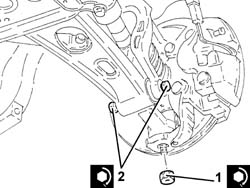
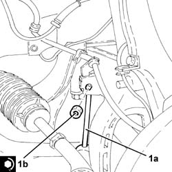
- Connect the front suspension anti-roll bar joints (1a) to the front shock absorber forks and secure them tightening the nuts (1b) to the recommended torque.
| Fastening | Component | Ø | Value (daNm) | |
|---|---|---|---|---|
| 1b | Nut | FRONT ANTI-ROLL BAR JOINTS | M10 | (Front shock absorber fork side) 4.1 - 5.0 |
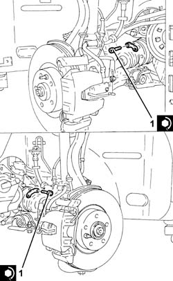
- Tighten the bolts fixing the driveshafts to the differential internal driveshaft/intermediate driveshaft to the recommended torque.
| Fastening | Component | Ø | Value (daNm) | |
|---|---|---|---|---|
| 1 | Bolt | DRIVESHAFT | M8 | (Differential internal driveshaft/intermediate driveshaft side) 3.6 - 4.4 |
- Remove the tools used for supporting the power unit safely.
- Place the bonnet lock in position and secure it using the nuts.
- Op. 1080B40 CATALYTIC PRE-CONVERTER - R R
- Op. 1072C44 EXHAUST MANIFOLD HEAT SHIELD ON BULKHEAD - R+R
- Op. 7055B54 UNDER-ENGINE GUARD - R R
- Op. 7055B66 ENGINE COMPARTMENT DUST SHIELD PROTECTION IN RIGHT FRONT WHEEL ARCH - R.R.
- Op. 7055B65 ENGINGE BAY DUSTGUARD PROTECTION IN LEFT FRONT WHEEL ARCH R R
- Op. 4450B12 FRONT OR REAR WHEELS (TWO) - R+R
- Op. 1016A40 IGNITION COIL COVER ON CYLINDER HEAD- R+R
- Remove the vehicle from the lift.
- Op. 4450A10 FRONT WHEEL GEOMETRY - CHECK USING OPTICAL EQUIPMENT - INCLUDES FRONT WHEEL TOW-IN ADJUSTMENT IF NECESSARY
Parts & tools for this job For 2003 Alfa Romeo GT
- TOOLCoil spring compressorSearch: coil spring compressor
- TOOLBall joint separatorSearch: ball joint separator
- PARTFront shock absorbersSearch: Alfa Romeo GT 2003 front shock absorbers
Links open Amazon search results in a new tab. As an Amazon Associate I earn from qualifying purchases.