
General description
- Make
- Alfa Romeo
- Model
- GTV / Spider GTV and Spider (916) Factory Service Manual
- Year
- 1995–2000
- Section
- 55-25 Heater › General description
GENERAL DESCRIPTION
Climate control through the heater is controlled by three knobs of the control unit located on the panel: these controls act on the heater-distributor-air flow unit as follows:
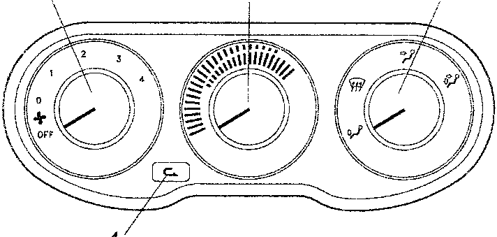
- the left-hand knob (1) mechanically operates the ports which adjust the flow of air: @PUNTO = OFF: air inlet shut off
- 0: inlet of outside air without fan (dynamic air)
- from 1 to 4: a switch is operated which turns on the fan through a four-speed regulator. The regulator and corresponding resistor are fitted on the airflow unit near the fan.
- the centre knob (2) - mechanically operates the mixing port between warm air (red) and cold air (blue): when turned completely to the left, it shuts off the radiator closing a special tap.
NOTE: the radiator comprises a heat exchanger which exploits the engine coolant fluid to warm the air sent to the passenger compartment: in fact it is supplied by a special pipe of the engine cooling circuit.
- the right-hand knob (3) adjusts the distribution of the flow acting, still by a mechanical transmission, on the distribution ports, sending air into the passenger compartment in the directions shown schematically on the ideograms.
- the recirculation function takes place pressing push-button (4) which acts on a motor that moves a flap: this closes the outside air duct, simultaneously opening that of the air recirculating from inside the passenger compartment.
NOTE: the heater can only be turned on with the ignition key engaged.
The recirculation function makes it possible to withdraw the air to be treated from inside the passenger compartment, shutting off the flow of outside air which under certain circumstances might be unwanted: bad smells, smoke, unventilated tunnels, etc.
FUNCTIONAL DESCRIPTION
Fan:
The heating and ventilation fan Q1 is supplied with battery voltage via the key-operated services relay I35 - located in fusebox G1 -; in addition to the relay, the supply line also crosses fuse F13 of fusebox G1.
The fan motor Q1 is operated with an earth signal from the control knob Q4. This signal crosses the speed regulator Q5, comprising three resistances in series, the crossing of which determines the four different speeds, depending on the signal from the knob Q4: from pin 2 of connector B (1st speed), from pin 1 of connector B (2nd speed), from pin C of connector A (3rd speed) and lastly from pin B of connector A (4th speed) with a direct signal that does not cross the regulator Q5.
The regulator Q5 has a built-in thermal safety fuse which deactivates the circuit if the temperature exceeds 98°C.
Recirculation:
The recirculation function is carried out by operating motor Q27 according to the following supply logic:
- - pin 2 of Q27 always at earth;
- - 12 V at pin 3 of Q27: the motor turns engaging the recirculation function;
- - 12 V at pin 1 of Q27: the motor turns shutting off recirculation;
The function is turned on through switch B98, but with switch Q4 at "0", "1", etc...:
- switch B98 not pressed: recirculation not engaged;
- switch B98 pressed: recirculation engaged.
N.B.: With switch Q4 at "OFF" recirculation is still activated, regardless of the position of switch B98
Controls lighting:
Lights F8a and F8b, inside the control panel together with the leds next to switch B98 are supplied by the sidelights circuit - connector D of fusebox G1.
NOTE: remember that the only functions controlled electrically are:
- - fan control and speed adjustment;
- - operating the "recirculation" function while the others are controlled mechanically.
Parts & tools for this job For 1995 Alfa Romeo GTV / Spider
- TOOLA/C manifold gauge setSearch: AC manifold gauge set
- TOOLUV leak detection kitSearch: AC UV leak detection kit
- PARTCabin filterSearch: Alfa Romeo GTV / Spider 1995 cabin filter
Links open Amazon search results in a new tab. As an Amazon Associate I earn from qualifying purchases.