
General description
- Make
- Alfa Romeo
- Model
- GTV / Spider GTV and Spider (916) Factory Service Manual
- Year
- 1995–2000
- Section
- 55-3 Fusebox › General description
GENERAL DESCRIPTION
This section describes the complete printed circuit that makes the connections inside the FUSEBOX G1.
In the various diagrams referring to the individual systems and circuits only the lines associated with the case under examination are shown: this chart gives a complete, overall view of the entire fusebox G1.
The fusebox houses a number of relays and other devices, shown here with the corresponding codes, and the fuses (F1,..., F24).
NOTE: not all the output pins of the box G1 are actually connected for all versions of the car: some lines therefore may be found to be redundant though they will be present on the printed circuit.
Next to the schematic drawings of the connectors a list of output signals from the different pins is given: this simplifies for instance faultfinding work on the different circuits affected. (NOTE: the letters N.C. indicate pins connected inside the fusebox but not used for the present versions of the car).
SUPPLY TO FUSEBOX
| PIN | CIRCUITS |
|---|---|
| - | Fusebox supply from terminal board |
| - | Direct supply for ignition switch, engine cooling fan, heater/conditioner fan, alarm control unit |
| - | Supply for power windows, door locking device, rearscreen, roof lights, sun roof (Gtv), automatic hood (Spider) |
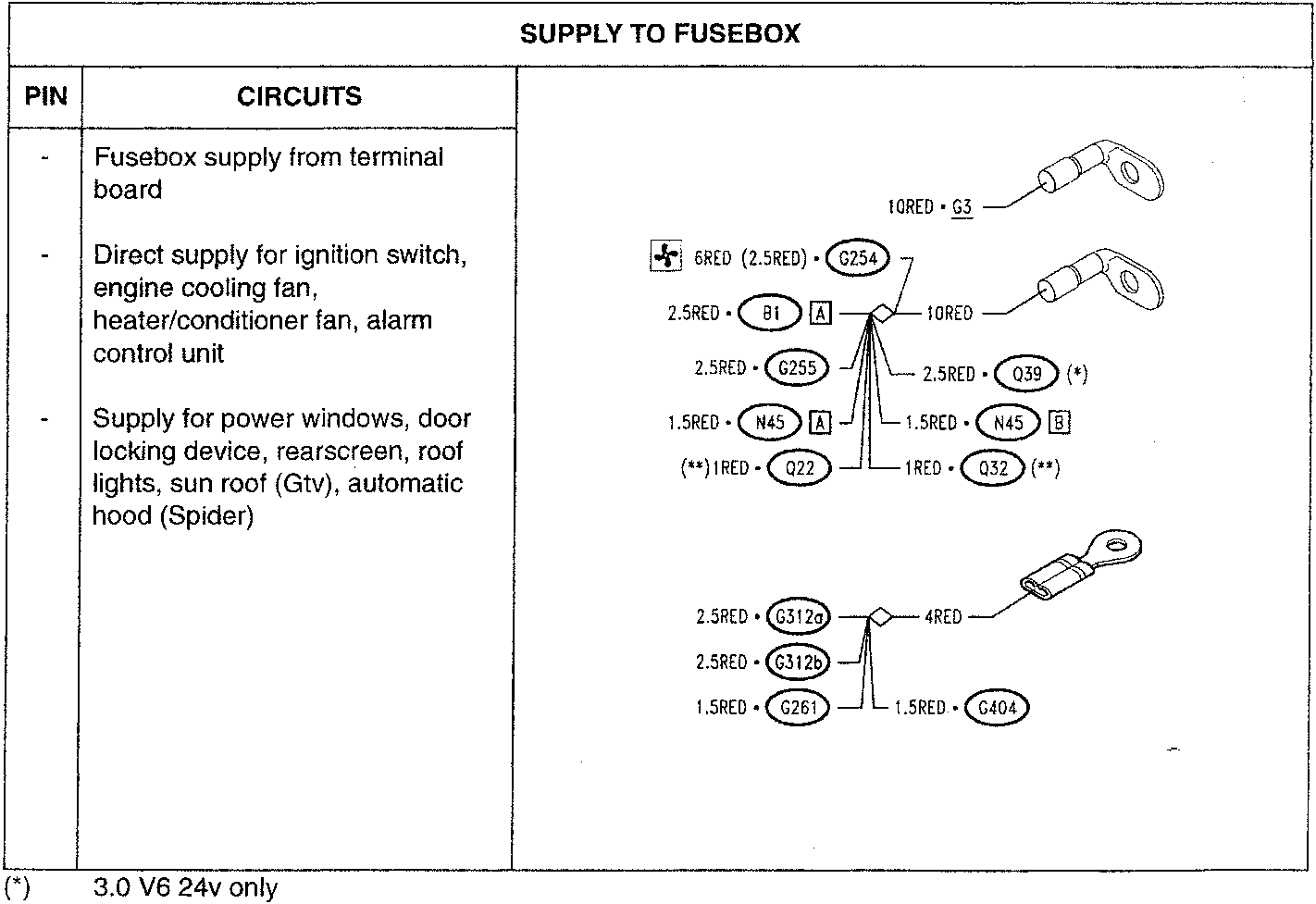
(*) 3.0 V6 24v only
(**) 2.0 TS 16v only
Parts & tools for this job For 1995 Alfa Romeo GTV / Spider
- TOOLTorque wrenchSearch: 3/8 inch torque wrench
- TOOLSocket setSearch: socket set metric
- BOOKHaynes manualSearch: Haynes manual Alfa Romeo GTV / Spider
Links open Amazon search results in a new tab. As an Amazon Associate I earn from qualifying purchases.