
General description
- Make
- Alfa Romeo
- Model
- GTV / Spider GTV and Spider (916) Factory Service Manual
- Year
- 1995–2000
- Section
- 55-14 Car radio › General description
GENERAL DESCRIPTION
The car is fitted with a provision for the installation of a car radio system complete with loud speakers.
The system includes all the wirings necessary, already connected to the "base" wiring loom of the car, with two 130x180mm front loudspeakers with 2 separate tweeters, and two 165 mm, two-way rear loudspeakers (GTV) or a single 165 mm rear sub-woofer loudspeaker (SPIDER).
The front speakers are located at the sides in the lower sections of the doors, with the tweeters on the pillar and the rear ones are on the shelf behind the seat (GTV) or in the centre behind the console (SPIDER).
The electric aerial is extended by a motor operated when the radio is switched on; it is located on the lefthand side of the boot lid and is connected with the radio by a coaxial cable.
The pre-installed supply for the radio is both key-operated and direct from the battery; this also makes it possible to memorise tuning, safety codes, etc. in the radio set.
In order to ensure very high sound quality under all conditions of use, a number of anti-disturbance suppressors have been fitted: this enables "electronic silencing" of the electric services that might interfere on the radio circuit:
- a suppressor in the boot lock;
- an aluminium sheet on the bonnet sound-deadening, earthed with a suitable braid;
- two condensers on the radio power supply.
FUNCTIONAL DESCRIPTION
The radio O4 is supplied directly by the battery voltage via fuse F2 (F16 from '98 version) of fusebox G1, at pin 4 and at pin 7 of connector B. Pin 8 of connector B is earthed.
Pin 6 receives the "sidelights on" signal used for lighting the radio controls.
The cables with the signals to the speakers leave from connector A of O4.
The aerial A3 is connected to the radio by the special screened coaxial cable G65.
A signal also leaves pin 5 of connector B of O4 which operates the motor of the electric aerial and extends it completely; when the radio signal ceases, the motor is operated in the reverse direction and the aerial is retracted completely.
The aerial A3 is powered via the line of fuse F16 of G1.
The suppressor N79 is inserted on the radio supply. Other suppressors are to be found near the services that would be more likely to interfere on the radio circuit.
CLARION RADIO
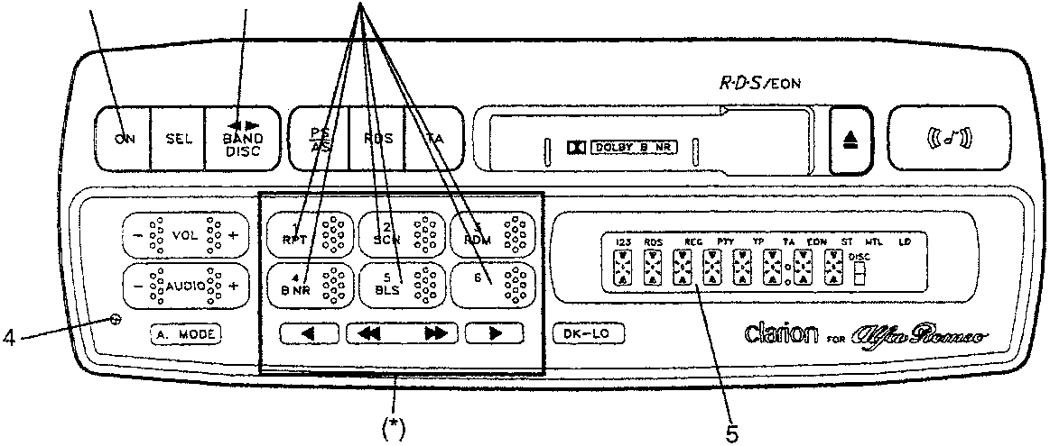
NOTE: For further details about the radio, see the base manual, or the handbook provided with the radio.
- ON/OFF switch
- Frequency band selector
- Pre-select buttons
- Antitheft led
- Display
- Removable control panel
Parts & tools for this job For 1995 Alfa Romeo GTV / Spider
- TOOLTorque wrenchSearch: 3/8 inch torque wrench
- TOOLSocket setSearch: socket set metric
- BOOKHaynes manualSearch: Haynes manual Alfa Romeo GTV / Spider
Links open Amazon search results in a new tab. As an Amazon Associate I earn from qualifying purchases.