
Removal/refitting
- Make
- Alfa Romeo
- Model
- GTV / Spider GTV and Spider (916) Factory Service Manual
- Year
- 1995–2000
- Section
- Electrical components › Removal/refitting
REMOVAL/REFITTING
- Disconnect the battery (-) terminal.
- Disconnect the coolant delivery sleeve to the radiator from the thermostatic cup and recover the fluid that comes out.
- Disconnect the electrical connection, then remove the coolant fluid temperature sensor from the thermostatic cup.
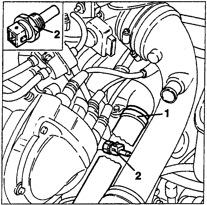
- sensor
- electrical connector
INERTIAL SWITCH
In the front side of the driver’s seat there is a safety switch which is triggered in the case of an impact, cutting off the fuel pump connection to earth, thereby also the supply to the injection system.
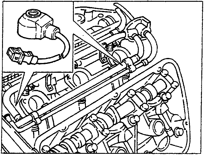
PINGING SENSORS
The pinging sensors are to be found on the crankcase, at the centre of the two cylinder heads. They comprise a piezoelectric plate and a seismic mass buried in a plastic mould. Their purpose is to detect the vibrations produced when the engine is running, exploiting a particular characteristic of piezoelectric materials which generate an output voltage when they are subjected to mechanical stresses.
This voltage is filtered and analyzed by the ignition control unit, which then adjusts spark angle in the "delay" direction, to command the injection control unit to enrich the fuel and reduce the boosting pressure.
As the boosting pressure falls the ignition control unit adjusts the spark angle again until the optimum rating is reached.
The detection and limiting of pinging take place for each cylinder.
As the pinging signals are allocated to the corresponding cylinder (by the 1st cylinder detection sensor), it is possible to adjust for each cylinder.
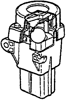
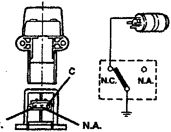
A steel ball fitted in a taper housing is normally held in place by the force of attraction of an adjacent magnet. Under specific acceleration loads the ball releases itself from the magnetic force and gradually moves out of the taper support rising upwards following the angle of the taper. A quick snap connection is fitted above the ball which forms the normally closed (N.C.) electric circuit. When the mechanism is hit by the ball it changes position, from N.C. circuit to normally open circuit (N.A.), cutting off the fuel pump earth circuit. In the event of impact in any one of the three orthogonal directions, the switch will be triggered above 12 g peak equivalent to a speed of 25 kph. The switch can be reset pressing the pushbutton protected by a flexible cover (this also protects against foreign particles which might prevent the switch from operating or reprogramme it).
Parts & tools for this job For 1995 Alfa Romeo GTV / Spider
- TOOLDigital multimeterSearch: automotive digital multimeter
- PARTAssorted fuse kitSearch: car fuse assortment kit
- TOOLWire crimper and connector kitSearch: wire crimper connector kit
Links open Amazon search results in a new tab. As an Amazon Associate I earn from qualifying purchases.