
Rpm and phase sensor
- Make
- Alfa Romeo
- Model
- GTV / Spider GTV and Spider (916) Factory Service Manual
- Year
- 1995–2000
- Section
- Electrical components › Rpm and phase sensor
RPM AND PHASE SENSOR
This sensor is fitted on the crankcase and faces the phonic wheel on the flywheel.
It is inductive, i.e. it works by means of the variations in the magnetic field generated by the passage of the phonic wheel teeth (60 - 2 teeth).
The injection ECU uses the rpm sensor signal to:
- - define revolution speed
- - define crankshaft angular position.
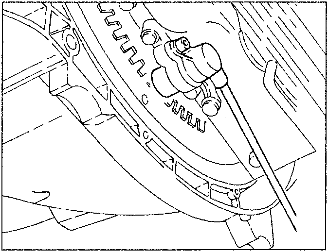
Operation
The switchover from full to none, due to the presence or the absence of a tooth, causes magnetic flow variations which generate an induced alternated voltage by counting the teeth on the phonic wheel.
The frequency and the width of the voltage sent to the ECU provides the engine angular speed measurement.
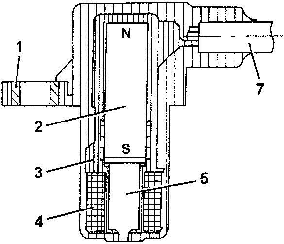
- Brass bushing
- Permanent magnet
- Plastic sensor casing
- Coil winding
- Pole core
- Crown or phonic wheel
- Co-axial double wire or electrical connection
The prescribed gap between the sensor tip and the phonic wheel for correct signals must be between 0.8 and 1.5 mm.
The gap cannot be adjusted. If the gap is out of tolerance, check intactness of sensor and phonic wheel.
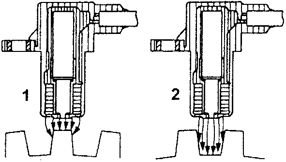
- Maximum magnetic flow
- Minimum magnetic flow
- Induced alternating voltage trend.
REMOVAL/REFITTING
- - Position the vehicle on a shop jack.
- - Make sure the ignition key is at "STOP" and disconnect the (-) battery terminal.
Parts & tools for this job For 1995 Alfa Romeo GTV / Spider
- TOOLOBD2 scannerSearch: OBD2 scanner
- TOOLDigital multimeterSearch: automotive digital multimeter
- TOOLBack-probe test leadsSearch: back probe test leads
Links open Amazon search results in a new tab. As an Amazon Associate I earn from qualifying purchases.